ACS550-02/U2 User’s Manual 37
Installation
Installation procedure
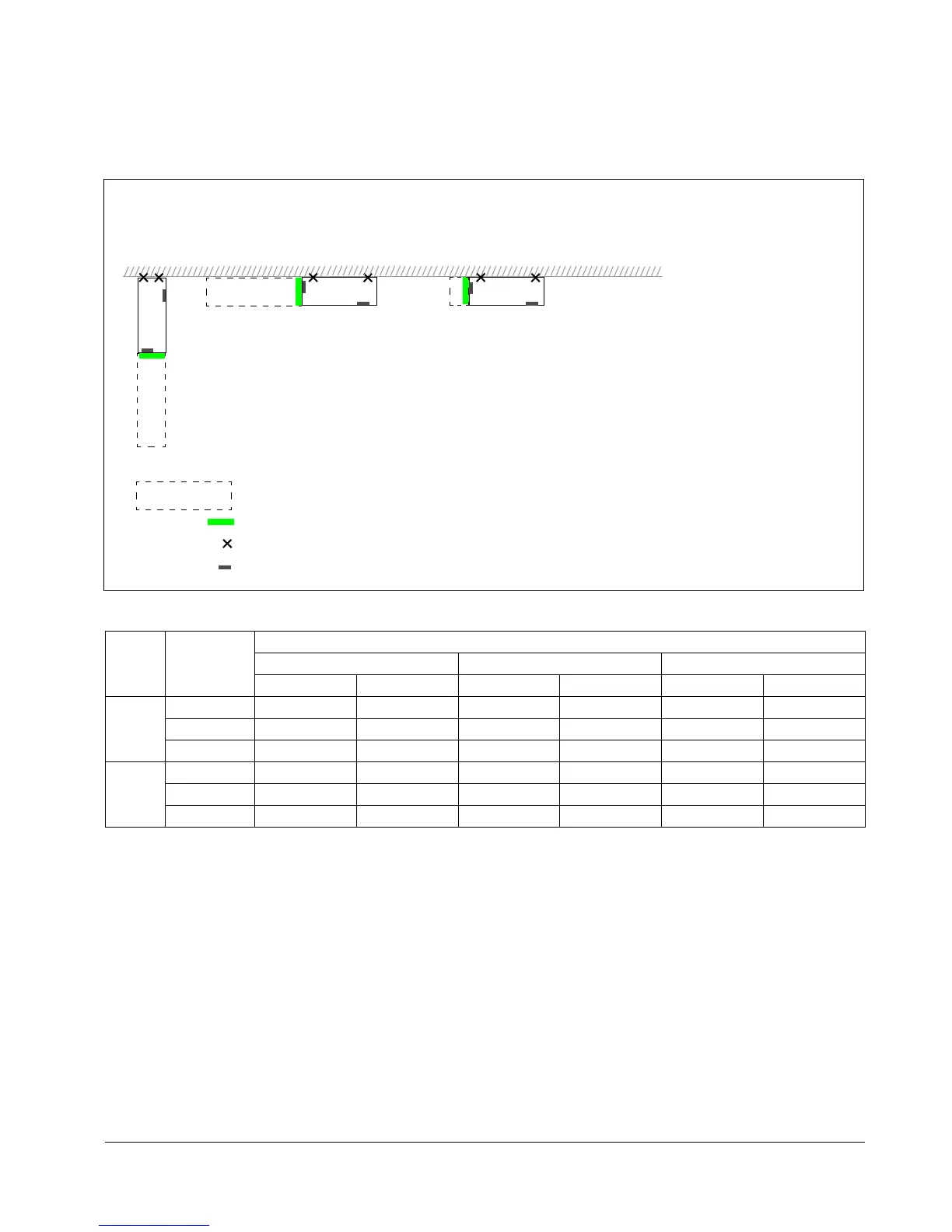
Choose the mounting orientation (a, b, or c)
* space for the installer not included
** space for fan and capacitor replacement not included
Preparing the mounting location on concrete floor
Bare (concrete) floor where cables come through openings made on the floor below
the drive. The floor or floor material of the installation place should not be flammable.
1. Lift the drive against the wall into the mounting place.
2. Mark the locations for the two fixing points in the wall.
3. Mark the bottom edges of the drive to the floor.
Frame
size
Mounting
orientation
Required free space around the drive for mounting, maintenance, service and cooling *
Front Side Above
mm in mm in mm in
R7 a 500 20 - - 200 7.9
b - - 500 20 200 7.9
c - - 200** 7.9** lifting space lifting space
R8 a 600 24 - - 300 12
b - - 600 24 300 12
c - - 300** 12** lifting space lifting space
a) b) c)
Symbols:
Lifted from above
required free space
wall fixing point (recommended)
air inlet surface
control panel mounting slot
Note: The drive can also be installed away
from the wall.

 Loading...


