a
b
a>b
OR
|I
OP
|
STINx
AND
HarmRestrainx=Disabled
INx>
BLKSTx
BLOCK
OR
2ndH_BLOCK_Int
Characteristn=DefTime
DirModex=Off
DirModex=Non-directional
DirModex=Forward
DirModex=Reverse
AND
AND
FORWARD_Int
REVERSE_Int
OR
OR
STEPx_DIR_Int
IEC09000638_3_en.vsd
Characteristn=Inverse
tx
min
AND
Inverse
tx
TRINx
AND
Characteristn= Inverse will be valid
for n = 1 and 4
IEC09000638 V3 EN
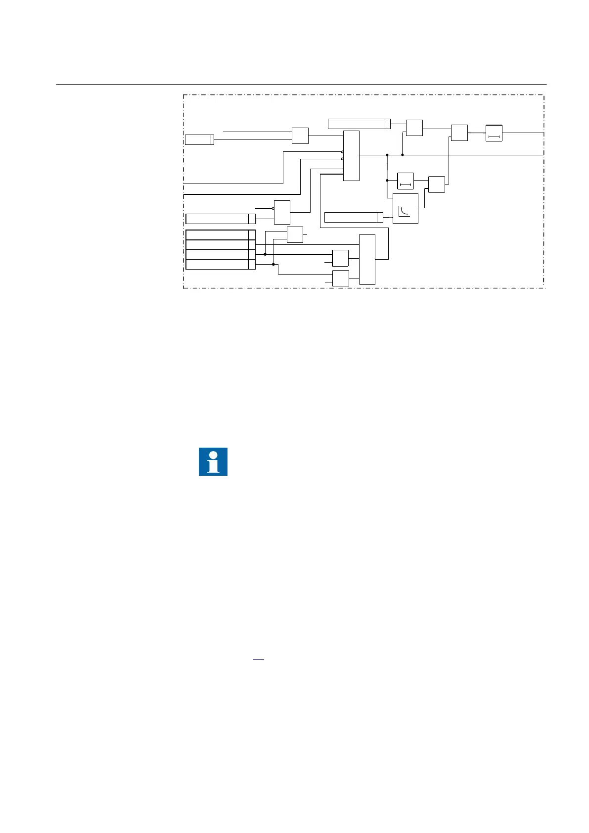
Figure 93: Simplified logic diagram for residual overcurrent
The protection can be completely blocked from the binary input BLOCK. Output
signals for respective step, STx and TRx and , can be blocked from the binary input
BLKSTx.
8.2.7.7 Directional supervision element with integrated directional comparison
function
It shall be noted that at least one of the four residual overcurrent steps
shall be set as directional in order to enable execution of the
directional supervision element and the integrated directional
comparison function.
The protection has integrated directional feature. The operating quantity current
I3PDIR is always used. The polarizinwcg method is determined by the parameter
setting polMethod. The polarizing quantity will be selected by the function in one of
the following three ways:
1. When polMethod = Voltage, UPol will be used as polarizing quantity.
2. When polMethod = Current, IPol will be used as polarizing quantity.
3. WhenpolMethod = Dual, UPol + IPol · ZNPol will be used as polarizing quantity.
The operating and polarizing quantity are then used inside the directional element, as
shown in figure
94, in order to determine the direction of the earth fault.
1MRK 502 048-UEN A Section 8
Current protection
197
Technical manual

 Loading...