8.8.5 Settings
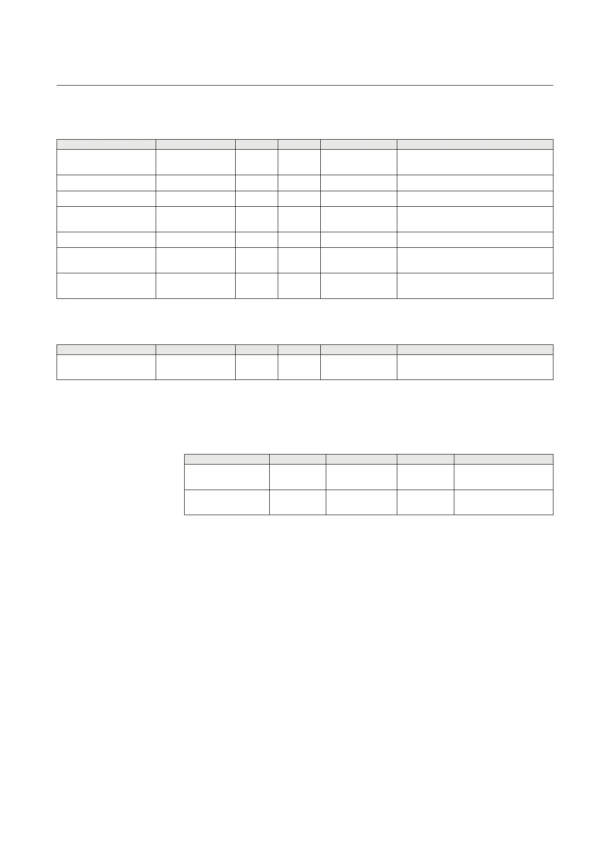
Table 137: AEGGAPC Group settings (basic)
Name
Values (Range) Unit Step Default Description
Operation Off
On
- - Off Operation Off / On
I> 5 - 900 %IB 1 120 Operate phase current level in % of IBase
tOC 0.000 - 60.000 s 0.001 0.030 Trip time delay for over current level
ArmU< 2 - 150 %UB 1 50 Under-voltage level to arm protection in %
of UBase
tArm 0.000 - 60.000 s 0.001 5.000 Time delay to arm protection with U< level
DisarmU> 2 - 200 %UB 1 80 Over-voltage level to disarm protection in
% of UBase
tDisarm 0.000 - 60.000 s 0.001 0.500 Time delay to disarm protection with U>
level
Table 138: AEGGAPC Non group settings (basic)
Name Values (Range) Unit Step Default Description
GlobalBaseSel 1 - 6 - 1 1 Selection of one of the Global Base Value
Groups
8.8.6 Monitored data
Table 139: AEGGAPC Monitored data
Name
Type Values (Range) Unit Description
IMAX REAL - A Maximum value of
current
UMAX REAL - kV Maximum value of phase
to phase voltage
8.8.7 Operation principle
Accidental energizing protection for synchronous generator AEGGAPC function is
connected to three phase current input either from the generator terminal side or from
generator neutral point side and three phase voltage from the generator terminals. The
maximum of the three phase-to-phase voltages and maximum of the three phase
currents are measured.
When the maximum phase-to-phase voltage is less than the ArmU< for the period
tArm, it is ensured that the generator is off-line. The ARMED signal will initiate the
arming and enable the overcurrent function. If the calculated maximum current of the
three phases is larger than I> for the period tOC then the TRIP signal becomes
activated. Also START signal becomes activated when overcurrent is detected.
1MRK 502 048-UEN A Section 8
Current protection
241
Technical manual

 Loading...