14.5.2 Function block
The Indications function has no function block of it’s own.
14.5.3 Signals
14.5.3.1 Input signals
The Indications function logs the same binary input signals as the Disturbance report
function.
14.5.4 Operation principle
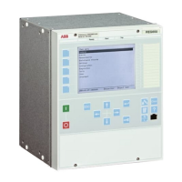
The LED indications display this information:
Green LED:
Steady light In Service
Flashing light Internal fail
Dark No power supply
Yellow LED:
Function controlled by SetLEDn setting in Disturbance report function.
Red LED:
Function controlled by SetLEDn setting in Disturbance report function.
Indication list:
The possible indication signals are the same as the ones chosen for the disturbance
report function and disturbance recorder.
The indication function tracks 0 to 1 changes of binary signals during the recording
period of the collection window. This means that constant logic zero, constant logic
one or state changes from logic one to logic zero will not be visible in the list of
indications. Signals are not time tagged. In order to be recorded in the list of
indications the:
• the signal must be connected to binary input BxRBDR function block
• the DRPRDRE parameter Operation must be set On
• the DRPRDRE must be trigged (binary or analog)
• the input signal must change state from logical 0 to 1 during the recording time.
Indications are selected with the indication mask (IndicationMask) when setting the
binary inputs.
Section 14 1MRK 502 048-UEN A
Monitoring
536
Technical manual

 Loading...