Table 532: Auxiliary voltage supply of 110...250 V DC or 100...240 V AC
Case Terminal Description
3U full 19” X420-1 - Input
X420-3 + Input
Table 533: Auxiliary voltage supply of 48-125 V DC
Case Terminal Description
3U full 19” X420-1 - Input
X420-2 + Input
Table 534: Auxiliary voltage supply of 24-30 V DC
Case Terminal Description
3U full 19” X420-3 - Input
X420-2 + Input
18.2.3 Binary inputs
The binary inputs can be used, for example, to generate a blocking signal, to unlatch
output contacts, to trigger the disturbance recorder or for remote control of IED
settings.
Each signal connector terminal is connected with one 0.5...2.5 mm
2
wire or with two
0.5...1.0 mm
2
wires.
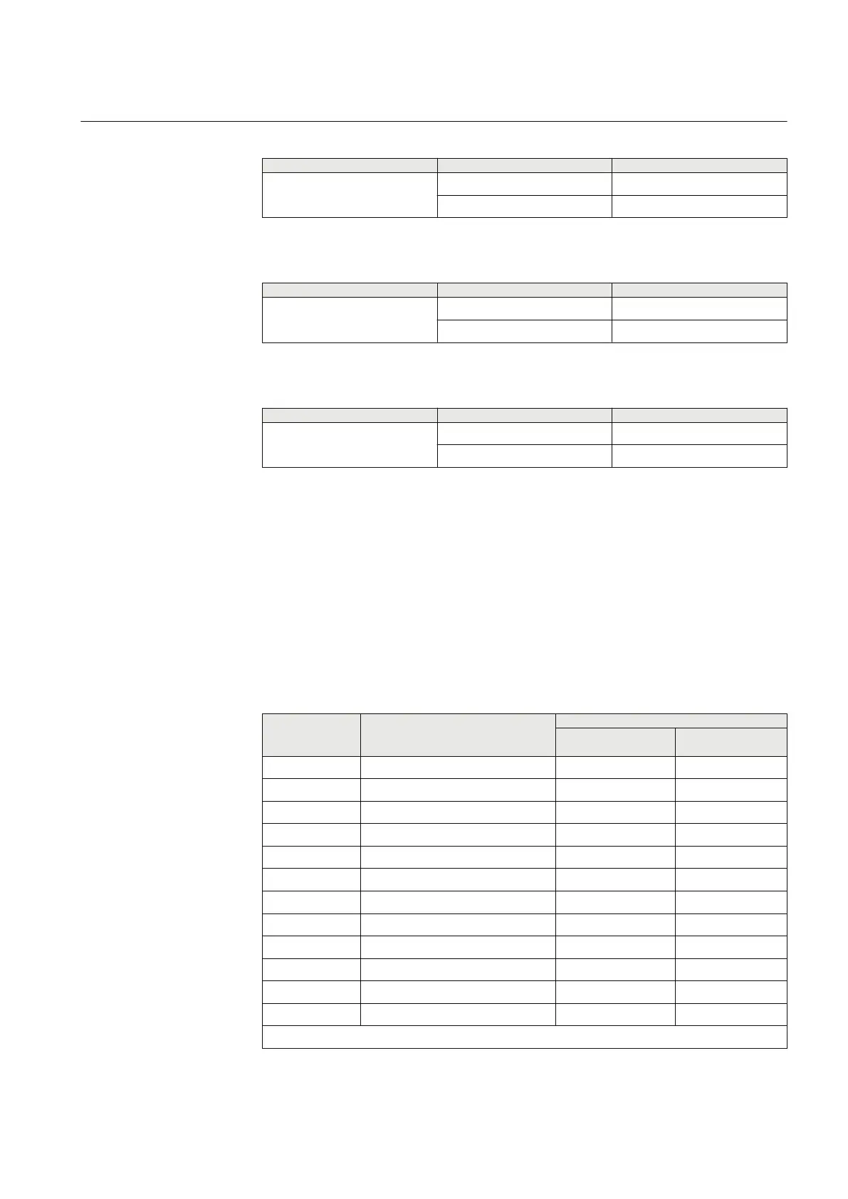
Table 535: Binary inputs X304, 3U full 19”
Terminal
Description
PCM600 info
Hardware module
instance
Hardware channel
X304-1 Common - for inputs 1-3
X304-2 Binary input 1 + COM_101 BI1
X304-3 Binary input 2 + COM_101 BI2
X304-4 Binary input 3 + COM_101 BI3
X304-5 Common - for inputs 4-6
X304-6 Binary input 4 + COM_101 BI4
X304-7 Binary input 5 + COM_101 BI5
X304-8 Binary input 6 + COM_101 BI6
X304-9 Common - for inputs 7-9
X304-10 Binary input 7 + COM_101 BI7
X304-11 Binary input 8 + COM_101 BI8
X304-12 Binary input 9 + COM_101 BI9
Table continues on next page
1MRK 502 048-UEN A Section 18
IED physical connections
661
Technical manual

 Loading...