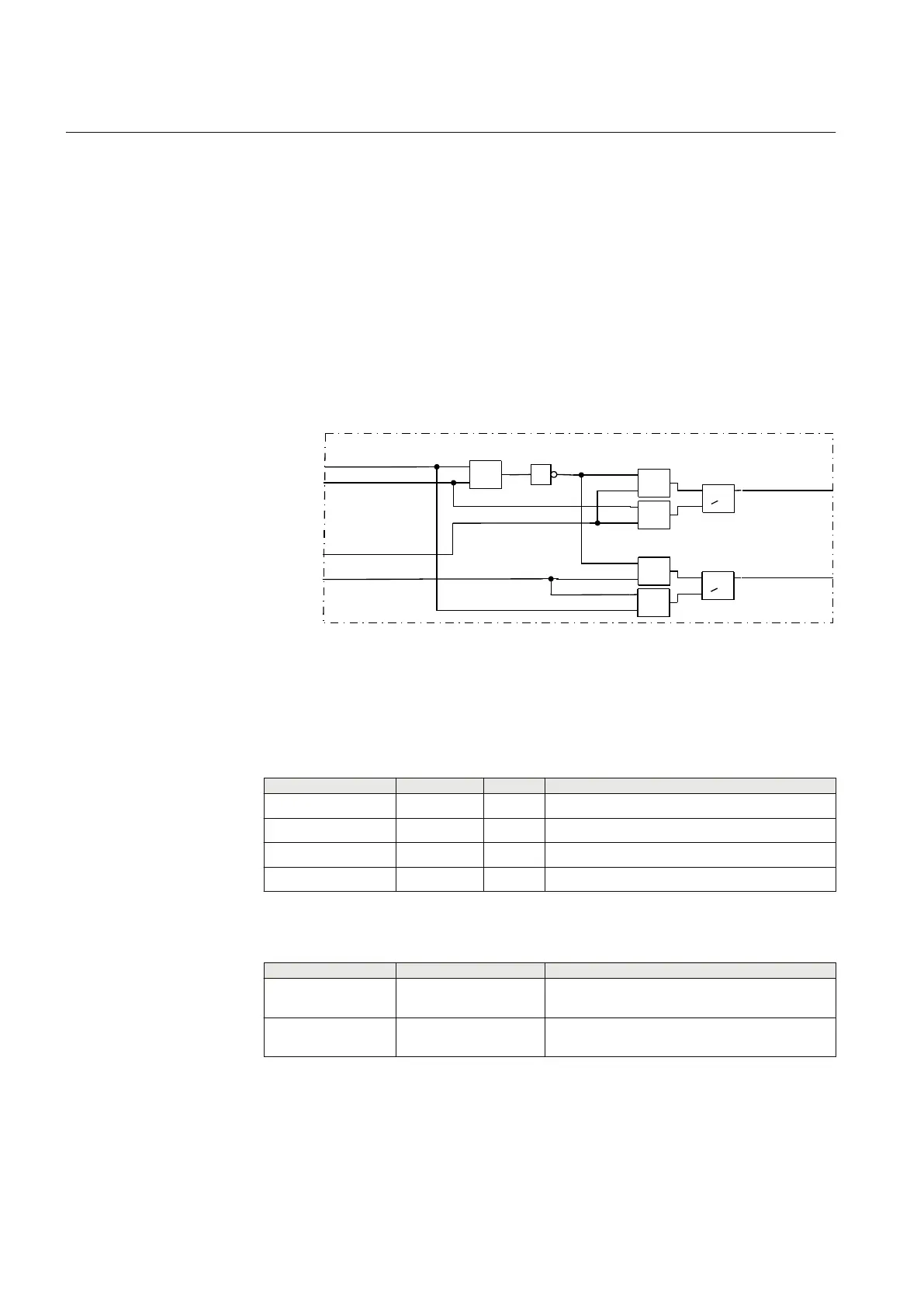
12.3.2.4 Logic diagram
The function contains logic to enable the open and close commands respectively if the
interlocking conditions are fulfilled. That means also, if the switch being controlled
has its position defined as open (via POSOPEN) for example, then the appropriate
enable signal output (in this case EN_OPEN) is false. The switch operation enable
signals EN_OPEN and EN_CLOSE can be true at the same time only in the
intermediate and bad position state of the switch (defined via POSOPEN and
POSCLOSE) and if they are enabled by the interlocking function. The position inputs
come from the logical nodes Circuit breaker/Circuit switch (SXCBR/SXSWI) and the
enable signals , OPEN_EN and CLOSE_EN come from the interlocking logic. The
outputs are connected to the logical node Switch controller (SCSWI). One instance
per switching device is needed.
OPEN_EN
POSOPEN
POSCLOSE
1
EN_OPEN
EN_CLOSECLOSE_EN
SCILO
=1
&
>1
>1
&
&
&
en04000525.vsd
IEC04000525 V1 EN
Figure 180: SCILO function logic diagram
12.3.2.5 Signals
Table 235: SCILO Input signals
Name
Type Default Description
POSOPEN BOOLEAN 0 Open position of switch device
POSCLOSE BOOLEAN 0 Closed position of switch device
OPEN_EN BOOLEAN 0 Open operation from interlocking logic is enabled
CLOSE_EN BOOLEAN 0 Close operation from interlocking logic is enabled
Table 236: SCILO Output signals
Name
Type Description
EN_OPEN BOOLEAN Open operation at closed or intermediate or bad
position is enabled
EN_CLOSE BOOLEAN Close operation at open or intermediate or bad
position is enabled
Section 12 1MRK 502 048-UEN A
Control
356
Technical manual
 Loading...


