Home
Atlas Copco
Construction Equipment
Dynapac F3030C
Atlas Copco Dynapac F3030C User Manual
4
of 1
of 1 rating
300 pages
Give review
Manual
Specs
To Next Page
To Next Page
To Previous Page
To Previous Page
Loading...
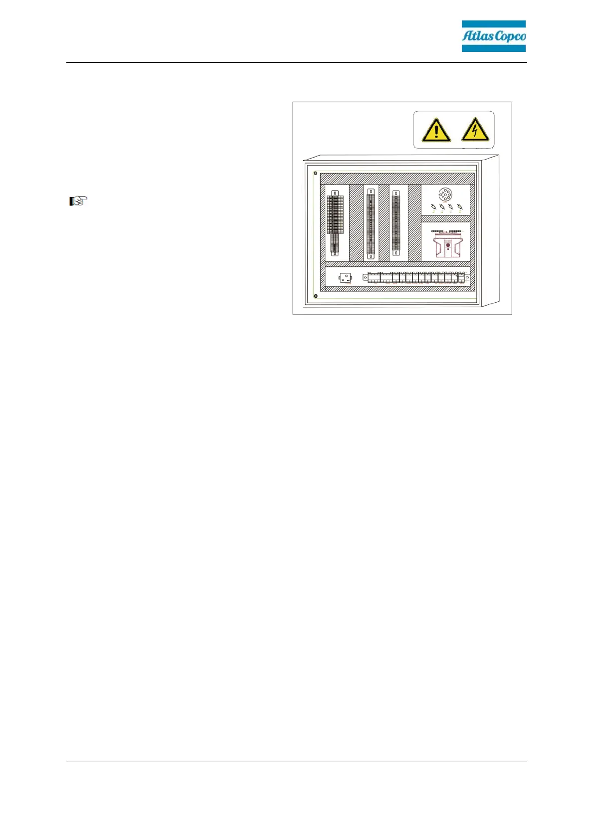
D30
7
Fuse box
The ter
minal b
ox, w
hich contains all
fuses and r
elays,
etc.,
is located
beneath
the ski
d of the central
control pl
atform.
An assig
nment
plan
f
or fus
es
and
relay
s can be found i
n chapter F8.
124
126
Table of Contents
Table of Contents
3
Preface
13
General Safety Instructions
14
Laws, Guidelines, Accident Prevention Regulations
14
Warnings
15
Prohibitive Symbols
17
Protective Equipment
18
Environment Protection
19
Fire Prevention
19
Additional Information
20
Guarantee Conditions
21
Residual Risks
22
Sensibly Predictable Incorrect Usage
23
A Correct Use and Application
25
B Vehicle Description
27
Application
27
Description of Assemblies and Functions
28
Vehicle
30
Construction
30
Danger Zones
34
Safety Devices
35
Technical Data, Standard Configuration
37
Dimensions (All Dimensions in MM)
37
Allowed Angle of Rise and Slope
38
Permissible Approach Angle
38
Weights F3030C (All Weights in T)
39
Performance Data F3030C
39
Travel Drive/Traction Unit
40
Engine F3030C
40
Hydraulic System
40
Material Compartment (Hopper)
40
Material Transfer
41
Material Distribution F3030C
41
Screed Lifting Device
41
Electrical System
42
Permissible Temperature Ranges
42
Location of Instruction Labels and Identification Plates
43
Identification Label for the Paver Finisher
45
Standards
46
Continuous Sound Pressuref3030C, Cummins QSB 6.7-C190
46
Operating Conditions During Measurement
46
Measuring Point Configuration
46
C11 Transportation
47
Satety Regulations for Transportation
47
Transportation on Low-Bed Trailers
48
Preparations
48
Driving Onto the Low-Bed Trailer
50
Secure the Paver Finisher to the Low-Bed Trailer
50
After Transportation
51
Protective Roof
52
Simple Roof
52
Fibre Glass Roof
53
Transportation
54
Preparations
54
Driving Mode
56
Loading by Crane
57
Towing
59
Safely Parking the Vehicle
61
D11 Operation
63
Safety Regulations
63
Controls
64
Operating Panel
64
Special Functions
89
Reversible Conveyor
89
Remote Control
90
Remote Control, Left Side
90
Remote Control, Right Side
94
D21 Operation
99
Display Terminal Description
99
Welcome Interface
99
Main Interface
100
Calibration Interface
102
Electrical System Input Parameter Monitoring
103
Propulsion System Output Parameters and Faults Monitoring Page
105
Electrical System Faults Monitoring Page
106
Engine Parameters
107
Engine Fault Display Page
109
Display Terminal Display Setting Page
110
Display Terminal Brightness Setting Page
111
Display Terminal Contrast Setting Page
112
Drive Engine Error Codes Correlation Table
113
D30 Operation
119
Operating Elements on the Paver Finisher
119
Control Elements on the Operator's Control Station
119
Protective Roof
119
Simple Roof
119
Fibre Glass Roof
120
Control Platform, Moveable
121
Driver's Seat, Type
124
Fuse Box
125
Batteries
126
Main Battery Switch
126
Hopper Transport Safeguard
127
Screed Lock, Mechanical (O)
128
Screed Lock, Hydraulic (O)
129
Paving Thickness Indicator
130
Auger Lighting (O)
130
Auger Height Adjustment Ratchet
131
Auger Height Indicators
131
Sensor Rod/Sensor Rod Extension
132
Conveyor Limit Switches - Conventional Version
134
Ultrasonic Auger Limit Switches (Left and Right)-PLC Version
135
Pressure Control Valve for Screed Charging/Relieving
136
Pressure Control Valve for Paving Stop with Relieving
136
Manometer for Screed Charging/Relieving
136
Central Lubrication System (O)
137
Screed Eccentric Adjustment
139
Offsetting the Screed
139
First-Aid Kit
142
Fire Extinguisher (O)
142
Operation
142
Preparing for Operation
143
Required Devices and Aids
143
Before Starting Work (in the Morning or When Starting Paving)
144
Check List for the Vehicle Operator
145
Starting the Paver Finisher
149
Before Starting the Paver Finisher
149
Normal" Starting
149
External Starting (Starting Aid)
151
After Starting
153
Observe Indicator Lamps
155
Battery Charge Indicator (1)
155
Engine Error Indicator (2)
155
Engine Inspection Indicator (3)
155
Engine Waiting-To-Start Indicator (4)
155
Preparation for Transportation
157
Driving and Stopping the Paver Finisher
159
Preparation for Paving
160
Separator Fluid
160
Screed Heater System
160
Direction Marks
160
Loading/Conveying Material
163
Starting for Paving
165
Checks During Paving
166
Paver Function
166
Quality of the Layer
166
Paving with "Screed Control at Paving Stop" and "Screed Charging / Relieving
167
General
167
Screed Charging/Relieving
169
Screed Control with Paver Finisher Stop/In Paving Operation
169
Adjusting the Pressure
169
Setting Pressure for Screed Control with Paving Stop + Relieving
170
Interrupting/Terminating Operation
173
During Breaks (E.g. the Material Supply Truck Is Late)
173
During Longer Breaks (E.g. Lunch Break)
173
When Work Is Finished
175
Malfunctions
176
Problems During Paving
176
Malfunctions on the Paver Finisher or Screed
178
Tips Regarding Material Laying
180
Layer Thickness
180
Joining Layers
182
Joining a Fresh Layer
182
Laying Asphalt over Manholes
182
E 11 Set-Up and Modification
185
Special Notes on Safety
185
Distribution Auger
186
Height Adjustment
186
Grain Sizes up to 16Mm
186
Grain Sizes > 16 MM
186
Mechanical Adjustment with Ratchet
187
Hydraulic Adjustment
187
Height Adjustment for Large Working Widths / with Brace
188
Auger Extension
189
Mounting the Auger Shaft Extension and Chute Plate
190
Auger Extension Chart
192
Working Width 2520Mm
193
Working Width 3094Mm
194
Working Width 3734Mm
195
Working Width 4983Mm
196
Working Width 5557Mm
197
Working Width 6197Mm
198
Working Width 7446Mm
199
Working Width 8020Mm
200
Working Width 8660Mm
201
Mounting the Auger Brace(Pull Rod)
202
Aligning the Auger
204
Offsetting the Screed
205
Levelling
206
Slope Controller
206
Mounting the Sensor Arm
207
Mounting the Grade Control System
207
Setting up the Sensor Arm
208
Big Ski 9 M, Big Ski 13 M
209
Mounting the Big Ski Bracket on the Crossbeam
211
Mounting the Swivel Arms
212
Mounting the Centre Element
213
Extending the Big Ski
214
Mounting the Sensor Bracket
215
Mounting and Aligning the Sensors
216
Mounting the Distributor Box
217
Connecting Diagram
218
Limit Switch
219
Auger Limit Switches (Left and Right) - Mouting the PLC Version
219
Screed
220
Electrical Connections
220
F10 Maintenance
221
Notes Regarding Safety
221
F22 Maintenance Review
223
F31 Maintenance - Conveyor
225
Maintenance - Conveyor
225
Maintenance Intervals
226
Points of Maintenance
227
Chain Tension, Conveyor
227
Replace Bottom Plate
228
Replace Conveyor Deflector
229
Check the Conveyor Drive Chain Tension
229
To Fill the Gear Oil
230
To Change the Gear Oil
230
F40 Maintenance - Auger Assembly
231
Maintenance - Auger Assembly
231
Maintenance Intervals
232
Check Tightening (6)
233
Mounting and Inspection
239
F50 Maintenance - Engine Assembly
241
Maintenance - Engine Assembly
241
Maintenance Intervals
242
Points of Maintenance
243
Engine Fuel Tank (1)
243
Engine Lube Oil System (2)
244
Engine Fuel System (3)
246
Engine Air Filter (4)
248
Engine Cooling System (5)
249
Engine Drive Belt (6)
251
F60 Maintenance - Hydraulic System
253
1. Maintenance - Hydraulic System
253
Maintenance Intervals
254
Hydraulic Oil Tank
254
Suction/Return Flow Hydraulic Filter
256
High-Pressure Filter
257
Bleeding the Filter
258
Hydraulic Hoses
259
Pump Distribution Gear
260
Bleeder
261
F74 Maintenance - Drive System
263
Maintence of Drive System
263
Maintenance Intervals
264
Point of Maintenance
266
Chain Tension (1)
266
Rubber Pads (2)
268
Rollers (3)
269
Planetary Gear (4)
270
Screw Connections
271
F81 Maintenance - Electrical System
273
Maintenance - Electrical System
273
Maintenance of Batteries
274
Fuses and Relays
274
F90 Maintenance - Lubricating Point
279
Maintenance
279
Maintenance - Points of Lubrication
280
Maintenance Interval
281
Maintenance Points
282
Central Lubrication System
283
Check Filling Level
283
Top up Lubricant Tank
283
Bleed Central Lubrication System
284
Check Pressure Limiting Valve
285
Check the Flow of Lubricant at the Consumers
286
Bearing Points
286
F100 Tests, Stopping
287
1. Tests, Checks, Cleaning, Stopping
287
Maintenance Intervals
288
General Inspection
288
Inspection by an Expert
288
Cleaning
290
Preserving the Paver Finisher
291
Shutdowns for up to 6 Months
291
Shutdowns Lasting from 6 Months to 1 Year
291
Recommissioning the Machine
291
F110 Lubricants and Operating Substances
293
Lubricants and Operating Substances
293
Capacities
295
Lubricant Specifications
296
Engine Oil
296
Coolant
296
Pump Distribution Gear Oil
296
Drive Unit Planetary Gear Oil
296
Auger Drive Planetary Gear Oil
296
Auger Box Gear Oil
296
Grease
296
Hydraulic System
297
4
Based on 1 rating
Ask a question
Give review
Questions and Answers:
Need help?
Do you have a question about the Atlas Copco Dynapac F3030C and is the answer not in the manual?
Ask a question
Atlas Copco Dynapac F3030C Specifications
General
Brand
Atlas Copco
Model
Dynapac F3030C
Category
Construction Equipment
Language
English
Related product manuals
Atlas Copco SmartROC D65 T4F
212 pages
Atlas Copco CS 14
14 pages
Atlas Copco HB 2000
72 pages
Atlas Copco HB 3100
68 pages
Atlas Copco LP 8504
41 pages
Atlas Copco HB Series
72 pages
Atlas Copco SmartROC T45
48 pages
Atlas Copco COBRA PROi 32
24 pages
Atlas Copco SECOROC COP 34
10 pages
Atlas Copco FlexiROC T30 R
144 pages
Atlas Copco FlexiROC T35 R
132 pages
Atlas Copco Cobra PROi ISO
24 pages