Home
GE
Medical Equipment
Venue Fit
GE Venue Fit User Manual
4
of 1
of 1 rating
300 pages
Give review
Manual
Specs
To Next Page
To Next Page
To Previous Page
To Previous Page
Loading...
DIRECTION 5854713-100, REVISION 2
VENUE FIT™ SERVICE MANUAL
Chapter 3 - Syst
em Setup
3-29
PRELIMINARY
3-6-2-5
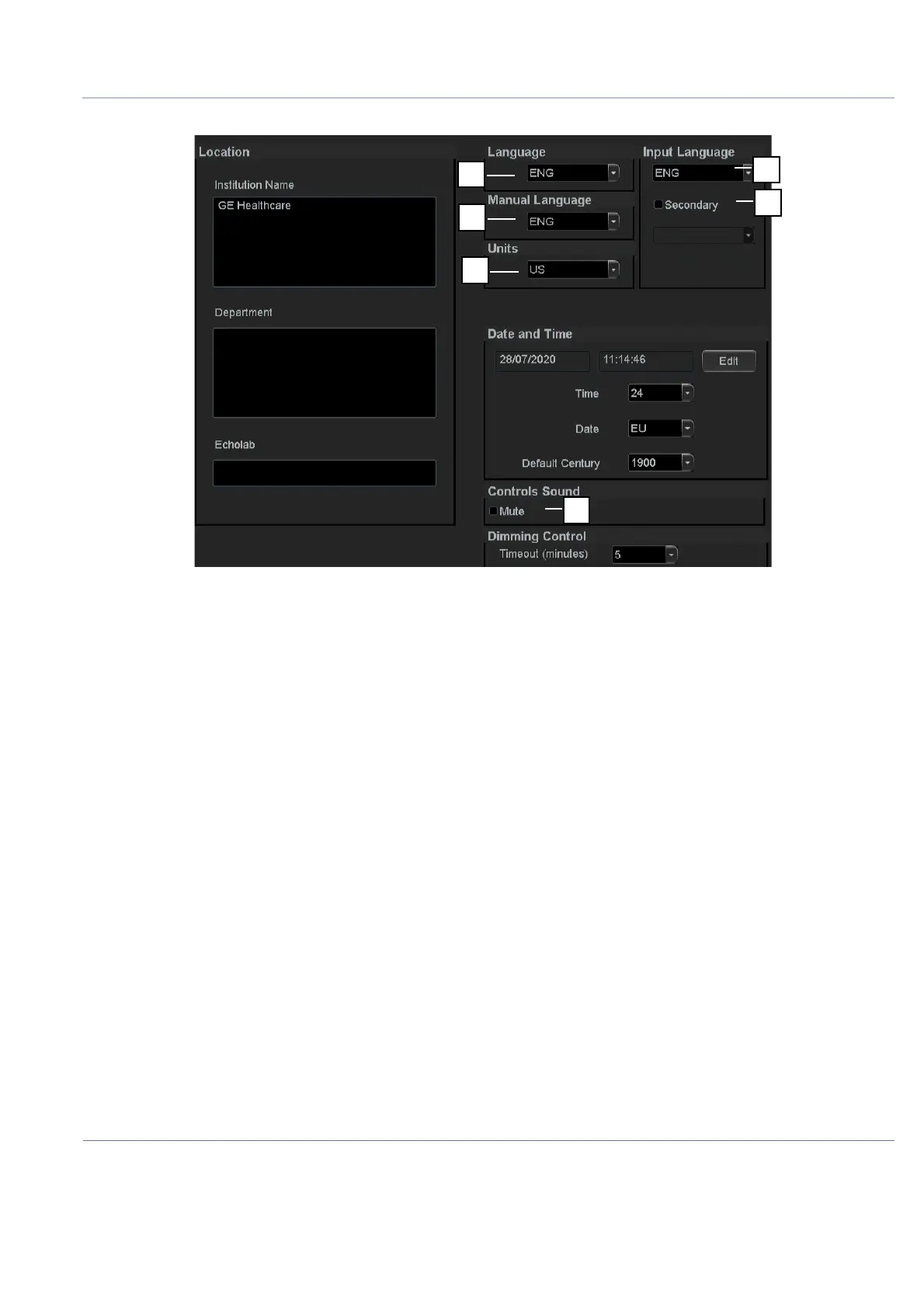
Select Language for Us
er Interface and Online Manuals
Figure
3-22 Select Language, Units
and Controls Sound
2
4
6
1
3
5
100
102
Table of Contents
default chapter
15
Table of Contents
15
Overview
28
Purpose of Chapter 1
28
Contents in this Service Manual
29
Service Manual Overview
29
Typical Users of the Basic Service Manual
29
Venue Fit™ Models Covered in this Manual
30
How to Check for Hardware/Software Version and Installed Options
31
How to Turn the Scanner on and off
31
Overview of the Venue Fit™ Ultrasound Scanner
31
Product Description
31
Conventions Used in this Manual
32
Icons
32
Important Conventions
32
Model Designations
32
Safety Precaution Messages
32
Standard Hazard Icons
33
Human Safety
35
Introduction
35
Safety Considerations
35
Mechanical Safety
38
Electrical Safety
40
Probes
40
Peripherals
41
Patient Data Safety
43
Venue Fit™ Battery Safety
43
Dangerous Procedure Warnings
44
Lockout/Tagout (LOTO) Requirements
45
Product Labels and Icons
46
Universal Product Labels
46
Label Descriptions
48
Venue Fit™ Cart Labels Location
50
Returning/Shipping Probes and Repair Parts
51
Electromagnetic Compatibility (EMC)
52
EMC, EMI, and ESD
52
Peripherals Used in the Patient Environment
52
Compliance
53
Electrostatic Discharge (ESD) Prevention
54
General Caution
54
Contact Information
55
Customer Assistance
55
CHAPTER 2: Site Preparations
57
Overview
57
Purpose of Chapter 2
57
Console Requirements
58
Unit Environmental Requirements
58
Cooling Requirements
58
Lighting Requirements
58
Time and Manpower Requirements
58
Electrical Requirements
59
Venue Fit™ Power Requirements
59
Inrush Current
59
Site Power Outlets
59
Mains Power Plug
59
Power Stability Requirements
60
EMI Limitations
60
EMI Prevention/Abatement
61
Probe Environmental Requirements
61
Time and Manpower Requirements
62
Facility Needs
63
Purchaser Responsibilities
63
Required Facility Needs
64
Suggested Minimal Floor Plan
65
Recommended Floor Plan
66
Desirable Features
67
Networking Pre-Installation Requirements
68
Stand-Alone Unit (Without Network Connection)
68
Unit Connected to Hospital's Network
68
Purpose of the DICOM Network Function
68
DICOM Option Pre-Installation Requirements
68
Connectivity Installation Worksheet
69
CHAPTER 3: System Setup
73
Overview
73
Purpose of Chapter 3
73
Setup Reminders
74
Average Setup Time
74
Setup Warnings
74
System Acclimation Time
74
Safety Reminders
74
Receiving and Unpacking the Equipment
76
Warnings for Receiving and Unpacking the Equipment
76
Overview
76
Unpacking Venue Fit™ System Sold as Stand Alone
78
Unpacking Venue Fit™ System Sold with a Cart
79
Physical Inspection
82
System Voltage Settings
82
EMI Protection
82
Preparing for Setup
83
Verifying Customer Order
83
Physical Inspection
83
Component Inspection
83
Damage Inspection Checklist
83
General View of the Venue Fit™ Ultrasound Unit
84
Venue Fit™ Cart Overview
85
Peripheral/Accessory Interface Panel
86
EMI Protection
86
Completing the Setup
87
Purpose of this Section
87
System Specifications
87
System Requirements Verification
87
Physical Dimensions
87
Mass with Monitor and Peripherals
87
Acoustic Noise Level
87
Electrical Specifications
88
Verification of the Venue Fit™ Voltage Setting
88
Electrical Specifications for the Venue Fit
88
Connections on the I/O Rear Panel
88
Network Connection
88
Connecting Probes
88
Introduction to Connecting Probes
88
Connect a Probe
90
Disconnect Probes
91
Power On/Boot up
91
Power Shut down
91
Complete Power down
91
Configuration
92
Purpose of this Section
92
Venue Fit™ Configuration
92
EZ Configuration Wizard
92
Select System Settings Screen
97
Enter Location
98
Adjust Date and Time
99
Select Language for User Interface and Online Manuals
101
Service Screen Setup
103
Open Service Screen
103
Optional Peripherals/Peripheral Connection
105
Approved Peripherals
105
Software Options Configuration
105
Software Option Introduction
105
Software Option Installation
105
Remote Check and Configurations
105
Connectivity Overview
106
Physical Connection
106
Stand-Alone Venue Fit
106
Wired Ethernet Connection
106
Wireless Connection
106
Connectivity Setup
107
Introduction
107
Select TCP/IP Screen
108
Finding the System Network MAC (Physical) Addresses
109
Set up Wireless Connection (for Broadcasting SSID Networks)
110
Setting up Non-Broadcasting (Hidden) Wireless Network Connection
111
Network Proxy/Dns/Wins Configuration
115
Proxy Setup
115
DNS/WINS Setup
116
Setup Qview
118
Qview Troubleshooting
118
Changing the AE Title And/Or Port Number (Port No.)
119
TLS - Transport Layer Security V1.2 Configuration
119
Background
119
Security LDAP Configuration
120
RSVP Configuration
122
Options Setup
124
Software Options
124
USB Flash Card Setup
124
Paperwork after Setup
125
Installation Acceptance Test Criteria
125
User's Manual(S)
125
Product Locator Installation Card
125
General Procedures and Functional Checks
126
Overview
126
Purpose of Chapter 4
126
General Procedures
127
Overview
127
Power On/Boot-Up
128
Warnings
128
Before Turning the System on for the First Time
128
Connecting the Venue Fit™ Ultrasound Unit to Power
129
Switch on the Venue Fit
129
Power Shutdown
129
Logging on to the Venue Fit™As "ADM
130
Open the Config Screen
130
The Login Dialog
130
Data Management
131
Backup
131
Deleting Patient Information
132
Transporting the Venue Fit™ Ultrasound Scanner
133
To Prepare the Venue Fit™ to be Moved
133
To Prepare the Venue Fit™ on Cart to be Moved
133
To Ensure Safety While Moving the Venue Fit™On Cart
133
Transporting the Venue Fit™ by Vehicle
133
Functional and Safety Checks
134
Overview
134
Phantoms Performance Checks
134
Image Quality Tests
135
2D Mode (B Mode) Checks
135
PW/CW Doppler Mode Checks
138
Probe/Connectors Check
141
Peripheral Checks
142
Printer Checks
142
ECG Functionality Checks
145
Mechanical Functions Checks
146
Kickstand Mechanical Checks
146
Cart Mechanical Checks
147
Functionality Tests
150
Battery Charging Test
150
Components and Function (Theory)
151
Overview
151
Purpose of Chapter 5
151
General Information
152
Introduction
152
Venue Fit™ Mechanical Design
152
System Configuration and Software
153
Electronics
153
Venue Fit™ System Design
154
Cart Overview
155
External Power Supply Section
156
Venue Fit™ User Interface Components
156
LED Indicators Modes
156
Battery Status Indication
156
Venue Fit™ Back End (M-BEB)
157
Back End
157
Back End Interfaces
157
Solid State Hard Drive
157
Compact Front End Board (C-FEB)
158
General Information
158
C-FEB Interfaces
158
Probe Selection Board (M-PSB)
159
Venue Fit™ Display
160
General
160
Display Panel Characteristics
160
Display Position Characteristics (with Venue Fit™ Mounted on Cart)
161
Multi Touch Layer
161
Speakers
161
External Input/Output
162
System Power Distribution
163
Introduction
163
System Monitoring
164
Power Management Controller
165
System Power Consumption
165
Rechargeable Battery Pack
165
Battery - General Safety Guidelines
165
Battery Chargers Requirements
166
Battery Power Specifications
167
Cooling System
168
General Information
168
Peripherals
169
Internal Peripheral
169
Wi-Fi Adapter
169
External Peripherals
169
Barcode Reader
169
Black & White Digital Graphic Printer
169
Ecg
169
Options
170
Connectivity
171
Purpose of this Section
171
Venue Fit™ and a DICOM Server in a Network
171
Rsvp/Insite - Remote Connectivity
172
Introduction
172
Insite Menu
172
Initiating a Request for Service
173
RFS History
174
Insite Status
175
Insite Definitions
176
Exiting Insite
176
CHAPTER 6: Service Adjustments
177
Overview
177
Purpose of Chapter 6
177
Diagnostics/Troubleshooting
178
Overview
178
Purpose of Chapter
178
Service Safety Considerations
179
Gathering Troubleshooting Data
180
Purpose of this Section
180
Running System Diagnostics
180
Request for Service (RFS)
181
Collect a 'Trouble Image' with Logs
181
Advanced Log Options
183
RSVP Service Desktop
184
Disruptive Mode
184
Color Status
185
Licenses
185
Home Screen
186
System Information
186
Software Status
189
Connected Probes
190
Gather Logs
190
Delete Files
191
Change Password
191
Third Party Software Licenses
194
SSA License
194
Network Capture
196
Options
197
Agent Configuration
202
Noise Troubleshooting
203
Purpose of this Section
203
Introduction
203
Overview of Types of Noise
203
Noise Picked up from the Air
203
Noise Received Via the External Cables
203
Intermittent Noise
204
Self-Generated Noise Generated Inside the Ultrasound System)
204
Heat Problems
204
Hardware Problems
205
Software Problems
205
Different Power Outlet
205
Different System
205
Different Location
205
Disconnect External Cables
205
Using a Loaner System During Faulty System Repair
206
Purpose of this Section
206
Transferring Data to the Loaner System
206
Replacement Procedures
211
Overview
211
Internal Parts- Replacement Procedures
212
Preparations
212
Battery Replacement Procedure
213
Tools
213
Time Required
213
Preparations
213
Battery Removal Procedure
214
Battery Installation Procedure
214
Kickstand Installation Procedure
215
Tools
215
Time Required
215
Preparations
215
Rear Cover Replacement Procedure
217
Tools
217
Time Required
217
Preparations
217
Rear Cover Removal Procedure
217
Rear Cover Installation Procedure
218
Speakers Replacement Procedure
219
Tools
219
Time Required
219
Preparations
219
Speakers Removal Procedure
219
Speakers Installation Procedure
220
M-PSB Replacement Procedure
221
Tools
221
Time Required
221
Preparations
221
M-PSB Installation Procedure
222
Fan Replacement Procedure
223
Tools
223
Time Required
223
Preparations
223
Fan Removal Procedure
223
Fan Installation Procedure
225
M-BEB and SSD Replacement Procedure
226
Tools
226
Time Required
226
Preparations
226
M-BEB Removal Procedure
226
M-BEB Installation Procedure
229
Power Shutdown C-FEB Replacement Procedure
230
Tools
230
Time Required
230
Preparations
230
C-FEB Removal Procedure
230
C-FEB Installation Procedure
232
Touch Display Assembly Replacement Procedure
233
Tools
233
Time Required
233
Preparations
233
Front Display Assembly Removal Procedure
233
Touch Display Assembly Installation Procedure
234
Mounting / Dismounting System on Cart
235
Tools
235
Time Required
235
Preparations
235
Dismounting System on Cart
235
Mounting System on Cart
237
Casters Replacement Procedure
238
Tools
238
Time Required
238
Preparations
238
Casters Removal Procedure
238
Casters Installation Procedure
238
Cart Cable Guides Replacement Procedure
239
Tools
239
Time Required
239
Preparations
239
8-2-13-4 Cart Cable Guides Removal Procedure
240
8-2-13-5 Cart Cable Guides Installation Procedure
241
ECG Replacement Procedure
242
Tools
242
Time Required
242
Preparations
242
ECG Removal Procedure
242
ECG Installation Procedure
243
ECG USB Cable Replacement Procedure
244
Tools
244
Time Required
244
Preparations
244
ECG USB Cable Removal Procedure
244
ECG USB Cable Installation Procedure
244
AC/DC PSU Replacement Procedure
245
Tools
245
Time Required
245
Preparations
245
PSU Removal Procedure
245
PSU Installation Procedure
246
Sony Printer Installation Procedure
247
Tools
247
Time Required
247
Preparations
247
Printer Installation Procedure
247
Software Loading Procedures
249
Software Installation/Update Procedures - General Overview
249
Preparation and Notes for Software Installation Procedure
249
Preparation and Notes for Software Upgrade Procedure
250
Software Installation Procedure
251
Run Venue Fit™ EZ Config Setup Wizard
253
Software Reload/Update Procedure
255
Backup System Configuration
255
Backup Patient Exams
257
Software Update Procedure
259
Software Recovery Procedure
262
Functional Checks to be Performed after Replacement Procedures
265
Submitting a Replacement Procedure Report
265
Required Functional Checks Per Replacement Part Category
266
CHAPTER 9: Renewal Parts
268
List of Abbreviations
269
Venue-Fit™ System on Cart Overview
270
Renewal Parts Lists and Diagrams
271
Mechanical Hardware Parts
271
System Parts
272
Cart Parts
274
Probes
275
Software Media
277
System Power Cables
278
Peripherals
280
CHAPTER 10: Care and Maintenance
282
Overview
282
Periodic Maintenance Inspections
282
Purpose of Chapter 10
282
Warnings
283
Why Perform Maintenance Procedures
284
Keeping Records
284
Quality Assurance
284
Maintenance Task Schedule
284
Tools Required
286
Tools Required for Servicing the Venue Fit
286
System Maintenance
287
Preliminary Checks
287
Functional Checks
288
System Checks
288
Peripheral/Option Checks
289
Mains Cable Inspection
289
Physical Inspection
290
Cleaning
291
General Cleaning
291
Cleaning the Touch Panel Display
292
Probe Maintenance
293
Probe Related Checks
293
Probe Handling
293
Basic Probe Care
293
Probe Cleaning
294
Basic Probe Cleaning
294
Returning and Shipping of Defective Probes
295
Electrical Safety Tests
296
Overview
296
Safety Test Overview
296
Outlet Test - Wiring Arrangement - USA and Canada
298
Grounding Continuity
298
4
Based on 1 rating
Ask a question
Give review
Questions and Answers:
Need help?
Do you have a question about the GE Venue Fit and is the answer not in the manual?
Ask a question
GE Venue Fit Specifications
General
Brand
GE
Model
Venue Fit
Category
Medical Equipment
Language
English
Related product manuals
GE Venue 50
289 pages
GE Venue Go
324 pages
GE Venue R1
478 pages
GE Venue R2
478 pages
GE LOGIQ e Vet
127 pages
GE LOGIQ S8 Vet
418 pages
GE LOGIQ P3 VET
348 pages
GE Versana Balance
431 pages
GE Versana Essential
305 pages
GE Vivid E9
802 pages
GE LOGIQ V2
317 pages
GE Vivid S6
690 pages