DIRECTION 5854713-100, REVISION 2
VENUE FIT™ SERVICE MANUAL
5-6 Chapter 5 - Components and Function (Theory)
PRELIMINARY
5-3-2 External Power Supply Section
The External Power Supply section provides power via the external AC/DC 24 V adapter.
5-3-3 Venue Fit™ User Interface Components
Status and Control panel contain the following functions:
• On/Off Touch Button with Green and Orange led indicator
• Internal Battery Status with Green and Orange Indicator
• Power adapter connection indicator
• Light Sensors
5-3-3-1 LED Indicators Modes
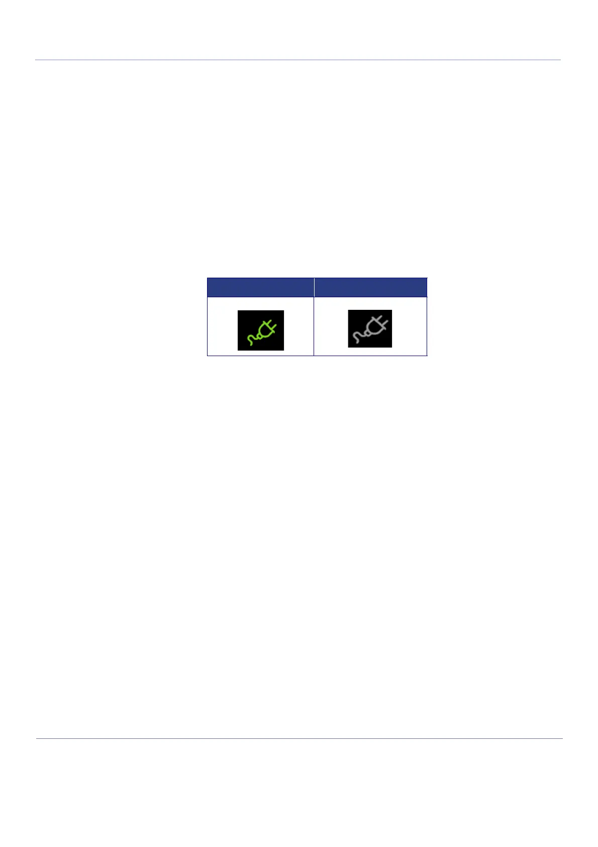
5-3-3-1-1 AC Power Indicator
5-3-3-1-2 Power On/Off Button States
The Power button frame provides additional indication of the current power supply state. When
pressing the On/Off button, the frame is highlighted with the same color as power indicator.
5-3-3-2 Battery Status Indication
The battery status indication is either red, orange or green and includes 6 light bars inside the battery
frame. The below figure shows all possible combinations.
Table 5-22 AC Power Indicator
ON OFF

 Loading...


