DIRECTION 5854713-100, REVISION 2
VENUE FIT™ SERVICE MANUAL
Chapter 10 - Care and Maintenance 10-17
PRELIMINARY
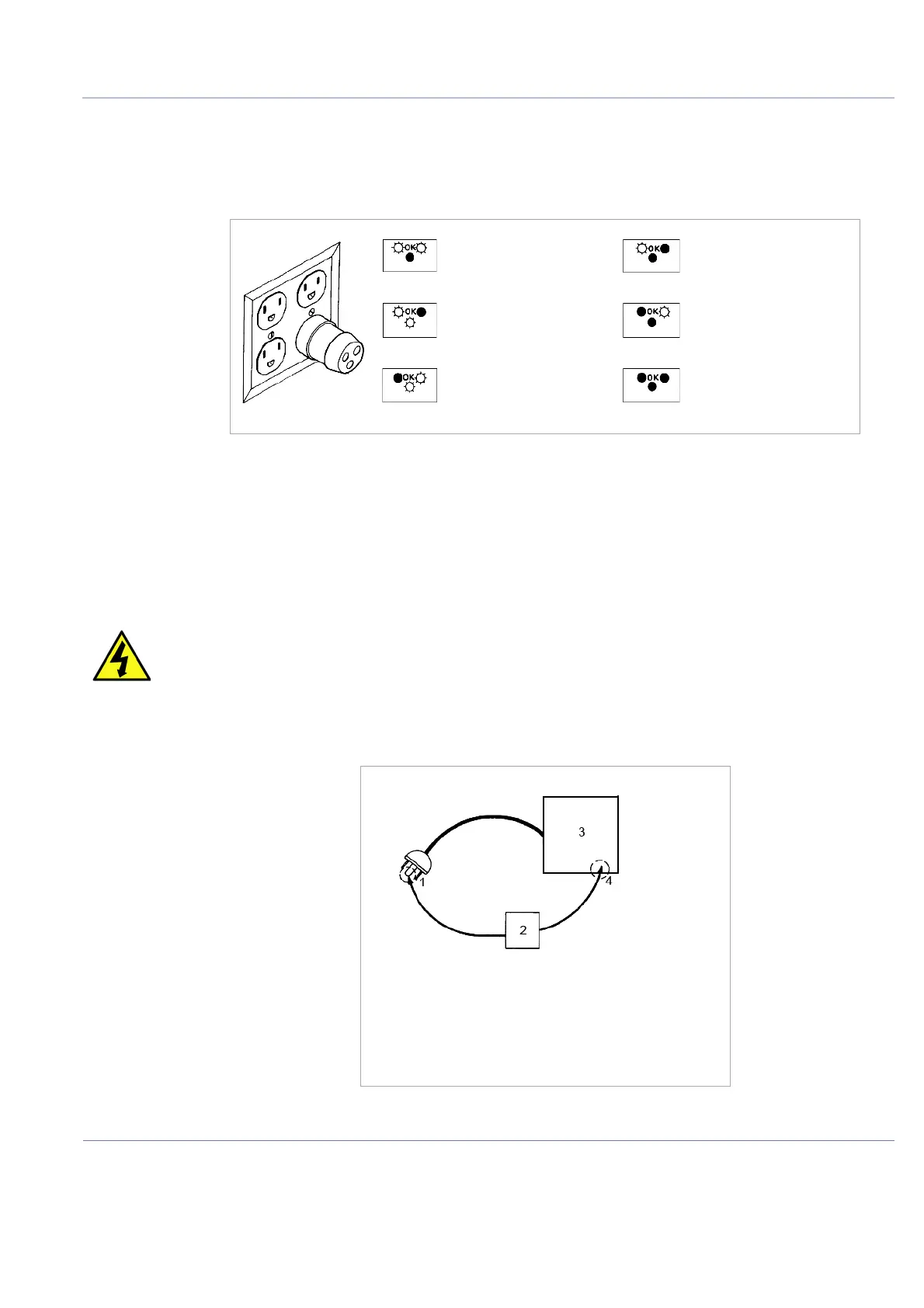
10-7-3 Outlet Test - Wiring Arrangement - USA and Canada
Test all outlets in the area for proper grounding and wiring arrangement by plugging in the neon outlet
tester and noting the combination of lights that are illuminated. Any problems found should be reported
to the hospital immediately and the receptacle should not be used.
NOTE: No outlet tester can detect the condition where the Neutral (grounded supply) conductor and the
Grounding (protective earth) conductor are reversed. If later tests indicate high leakage currents, this
should be suspected as a possible cause and the outlet wiring should be visually inspected.
10-7-4 Grounding Continuity
Measure the resistance from the third pin of the attachment plug to the exposed metal parts of the case.
The ground wire resistance should be less than 0.2 ohms. Reference the procedure in the IEC60601-1.
Figure 10-95 Typical Alternate Outlet Test
DANGER ELECTRIC SHOCK HAZARD. THE PATIENT MUST NOT BE CONTACTED TO THE
EQUIPMENT DURING THIS TEST.
Figure 10-96 Ground Continuity Test
CORRECT WIRING OPEN GROUND WIRE
REVERSED POLARITY OPEN NEUTRAL WIRE
HOT AND GROUND
REVERSED
OPEN HOT WIRE
1. GROUND PIN
2. OHMMETER
3. Venue Fit™
4. ACCESSIBLE METAL PART:
• MONITOR HOUSING
• REAR PANEL CONNECTOR
• ANY CASTER/WHEEL SUPPORT

 Loading...


