EasyManuals Logo

GE Versana Balance User Manual

GE Versana Balance
431 pages
To Next Page IconTo Next Page
To Previous Page IconTo Previous Page
Page #102 background imageLoading...
Page #102 background image
System Setup
3-22 System view Versana Balance – Basic Service Manual
5808768-100 English Rev.9
3-6-5 Peripherals/Accessories Connector Panel
Versana Balance peripherals and accessories can be properly
connected using the side connector panel.
Figure 3-4. Rear Connector Panel
1. DC out port DC 12V 1.5A Out
2. Diagnostic LED Diagnostic LED 1, Diagnostic LED 2, Diagnostic LED 3
3. Dual USB port USB for use
4. Ethernet 100MBase-T for net connectivity
5. USB port USB for use
6. HDMI port For video port
7. VGA VGA Video Out
8. Audio Out Audio Out
9. S-Video S-Video Out
10. Composite Out Composited Video Out
11. Circuit breaker Circuit breaker
12. AC Inlet 100-240V
13. GND Ground terminal

Table of Contents

Questions and Answers:

Question and Answer IconNeed help?

Do you have a question about the GE Versana Balance and is the answer not in the manual?

GE Versana Balance Specifications

General IconGeneral
CategoryUltrasound System
Doppler ModesColor Doppler, Power Doppler, Pulsed Wave Doppler, Continuous Wave Doppler
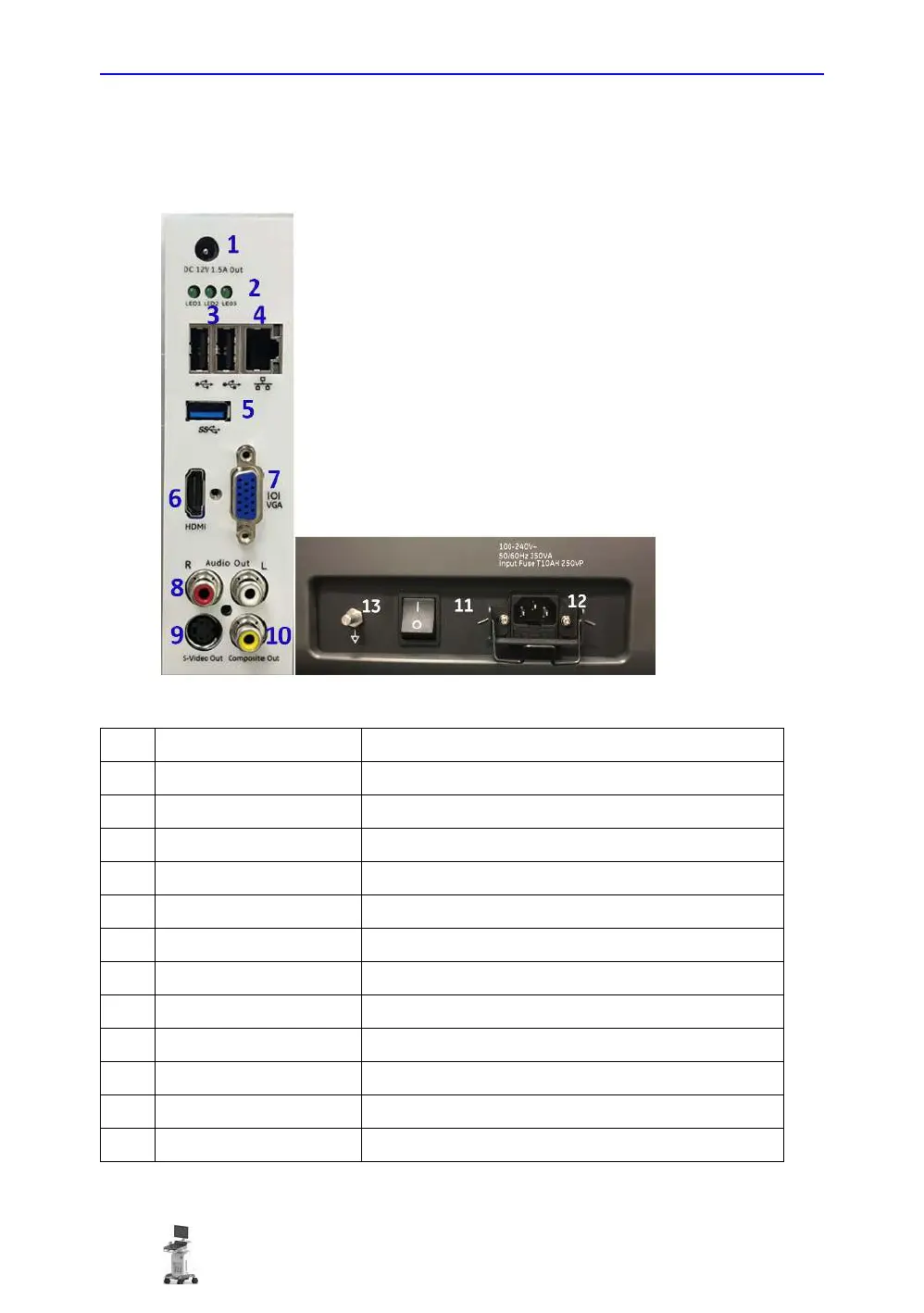
Power Requirements100-240 V AC, 50/60 Hz
DICOM CompatibilityYes
Wireless ConnectivityOptional
DisplayLED
Transducersconvex, linear, phased array
Image StorageUSB
ConnectivityUSB, HDMI, Ethernet, DICOM
ApplicationsObstetrics, Gynecology, Cardiology, Vascular, Urology
Imaging Modes2D, M-Mode, 3D/4D
Operating Temperature10°C to 40°C
Storage Temperature-20°C to +60°C
Humidity Range20% to 80% (non-condensing)
Display Size15.6 inches
Transducer Ports3 active transducer ports

Related product manuals