General Procedures and Functional Checks
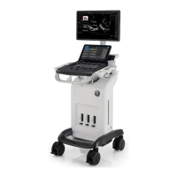
4-66 System view Versana Balance – Basic Service Manual
5808768-100 English Rev.9
4-4-13 Probe/Connectors Check
NOTE: Probes can be connected at any time, whether the unit is ON or
OFF.
4-4-13-1 To connect a Probe
1. Place the probe’s carrying case on a stable surface and
open the case.
2. Carefully remove the probe and unwrap the probe cable.
3. Put the porbe in the probe holder.
4. Hold the probe connector vertically with the cable pointing
upward.
5. Slide the connector lock to the left (unlocked position).
6. Align the connector with the probe port and carefully push
into place.
7. Slide the connector lock to the right position to secure the
probe connector.
8. Carefully position the probe cable in the probe cord holder
spot so it is free to move, but not resting on the floor.
DO NOT allow the probe head to hang free. Impact to the
probe head could result in irreparable damage.
TAKE THE FOLLOWING PRECAUTIONS WITH THE PROBE
CABELS:
-KEEP AWAY FROM THE WHEELS
-DO NOT BEND
-DO NOT CROSS CABLES BETWEEN PROBES
Table 4-1: Probe and Connectors Checks
Step Task Expected Results
1 Select the appropriate connected probe from
the probe indicators.
The probe activates in the currently-selected
operating mode. The probe’s default settings
for the mode and selected exam are used
automatically.
2 Launch the application. To change application,
press Probe key on the Control Panel.
The selected application starts.
3 Verify there’s no EMI/RFI or artifacts specific to
the probe.
No EMI/RFI or artifacts.

 Loading...