EasyManuals Logo

GE Versana Balance User Manual

GE Versana Balance
431 pages
To Next Page IconTo Next Page
To Previous Page IconTo Previous Page
Page #415 background imageLoading...
Page #415 background image
Electrical safety tests
Versana Balance – Basic Service Manual System view 10-25
5808768-100 English Rev.9
10-7-4 Grounding continuity
Measure the resistance from the third pin of the attachment plug
to the exposed metal parts of the case. The ground wire
resistance should be less than 0.2 ohms. Reference the
procedure in the IEC60601-1.
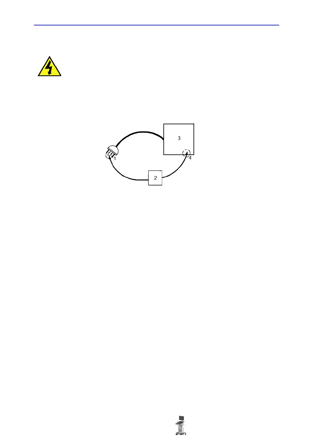
Figure 10-2. Ground continuity test
1. GROUND PIN
2. OHMMETER
3. Versana Balance
4. ACCESSIBLE METAL PART:
• MONITOR HOUSING
• PEAR PANEL CONNECTOR
• ANY CASTER/WHEEL SUPPORT
DANGER ELECTRIC SHOCK HAZARD. THE PATIENT MUST NOT BE
CONTACTED TO THE EQUIPMENT DURING THIS TEST.

Table of Contents

Questions and Answers:

Question and Answer IconNeed help?

Do you have a question about the GE Versana Balance and is the answer not in the manual?

GE Versana Balance Specifications

General IconGeneral
CategoryUltrasound System
Doppler ModesColor Doppler, Power Doppler, Pulsed Wave Doppler, Continuous Wave Doppler
Power Requirements100-240 V AC, 50/60 Hz
DICOM CompatibilityYes
Wireless ConnectivityOptional
DisplayLED
Transducersconvex, linear, phased array
Image StorageUSB
ConnectivityUSB, HDMI, Ethernet, DICOM
ApplicationsObstetrics, Gynecology, Cardiology, Vascular, Urology
Imaging Modes2D, M-Mode, 3D/4D
Operating Temperature10°C to 40°C
Storage Temperature-20°C to +60°C
Humidity Range20% to 80% (non-condensing)
Display Size15.6 inches
Transducer Ports3 active transducer ports

Related product manuals