43-TV-25-30 Iss.6 GLO Aug 07 UK 15
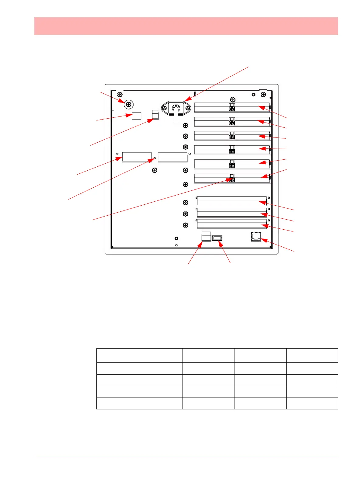
Card and Slot positions
“QXe Analogue Input (Standard) card” on page 19
Earth screw
(ground)
24V DC/AC Input
SPNC
Relay
24V TX
Power Supply
Output
LED
AC supply
100 - 250 VAC
Analogue Input/
Analogue Output/
or Pulse Input
Slot A
Slot B
Slot C
Slot D
Slot E
Slot F
Alarm Relay
or
Digital I/O
Slot G
Slot H
Slot I
Ethernet
RS485 USB Host
Figure 2.4 Multitrend SX Rear panel
CJC Sensor
position in the
middle of the
Analogue Input
connector.
Slots A - F
Table 2.1 : Card priority positions
Cards
Minitrend QX Multitrend SX eZtrend QXe
Analogue Input card A, B A, B, C, D, E, F A*, B (option)
Analogue Output card B E, F -
Pulse Input card A, B A, B, C, D, E, F -
Alarm Relay or Digital I/O card G G, H, I G
 Loading...