22 43-TV-25-30 Iss.6 GLO Aug 07 UK
Analogue Output Channel Numbers
The Analogue Output cards are either 2 or 4 channels using a connector that only takes up
half the length of the connector slot. Looking from the rear of the unit the Analogue Out con-
nector is on the left of the Analogue slot with a blanking plate on the right.
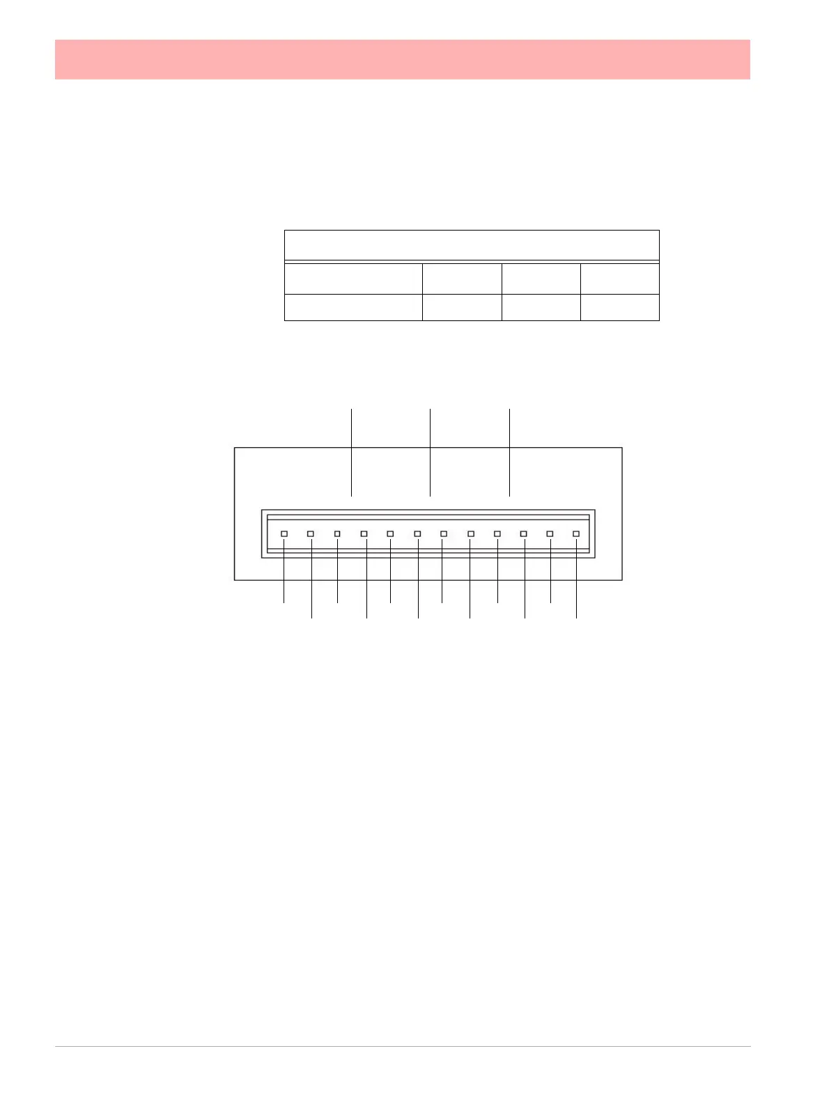
Analogue Output Connection Details
Pulse Input Card
The Pulse Input card connections are made via 1 x 12-way screw terminal plugs that fits
into a PCB header on the rear of the unit.
The Pulse Input card position for the Minitrend QX
is shown in Figure 2.3 on page 14,
and Figure 2.4 on page 15 for the Multitrend SX.
The Pulse Input card is not available on the eZtrend QXe
recorder, however, the 8 Digital I/
O option card has 4 channels that can be set as pulse inputs (channels 1 to 4). The operat-
ing frequency for pulse inputs on the Digital I/O card is 1kHz max.
Input: Low < 1V, High >4V to <50V DC (8V to 50V p-p AC) or Volt free input: Low = short
circuit, High = open circuit.
Table 2.4 :
Analogue Output card
Card Position
Slot B Slot E Slot F
Channel number 9 to 12 33 to 36 41 to 44
Output 1 Output 2 Output 3
Output 4
Loop -
Loop +
NC
Loop -
Loop +
NC
Loop -
Loop +
NC
Loop -
Loop +
NC
1 2 3 4 5 6 7 8 9 10 11 12
NC = Not
connected
 Loading...