43-TV-25-30 Iss.6 GLO Aug 07 UK 19
Recorder setup will be required if wiring changes are made for Active Burnout Thermocou-
ples. See “*Thermocouple Wiring Changes.” on page 57.
Thermocouple Active Burnout status can be viewed in the Main Menu > Status >Diagnostics
> Analogue Input screen, Input column. The Health Watch/Maintenance firmware option
must be active to access the Maintenance and Diagnostic buttons. See “Diagnostics” on
page 161.
For the eZtrend QXe
recorder Active Burnout is not available. Ohms measurements must have
the link between positive (+) and negative (-).
CJC Connectors
The CJC connector resides between channel 4 and channel 5 on the Analogue Input card.
For information on connecting the CJC sensor, see Figure 2.6 on page 18.
For the eZtrend QXe
recorder this is available on the Analogue Input card (option).
QXe Analogue Input (Standard) card
The eZtrend QXe is fitted with a standard Analogue Input card in Slot A, with up to 6 chan-
nels. The card is also fitted with an Ethernet port as standard. Connection is made via 1 x
18-way screw terminal plugs that fit into a PCB header on the rear of the unit. To fit up to a
further 6 analogue input channels, see “Analogue Input Card” on page 16
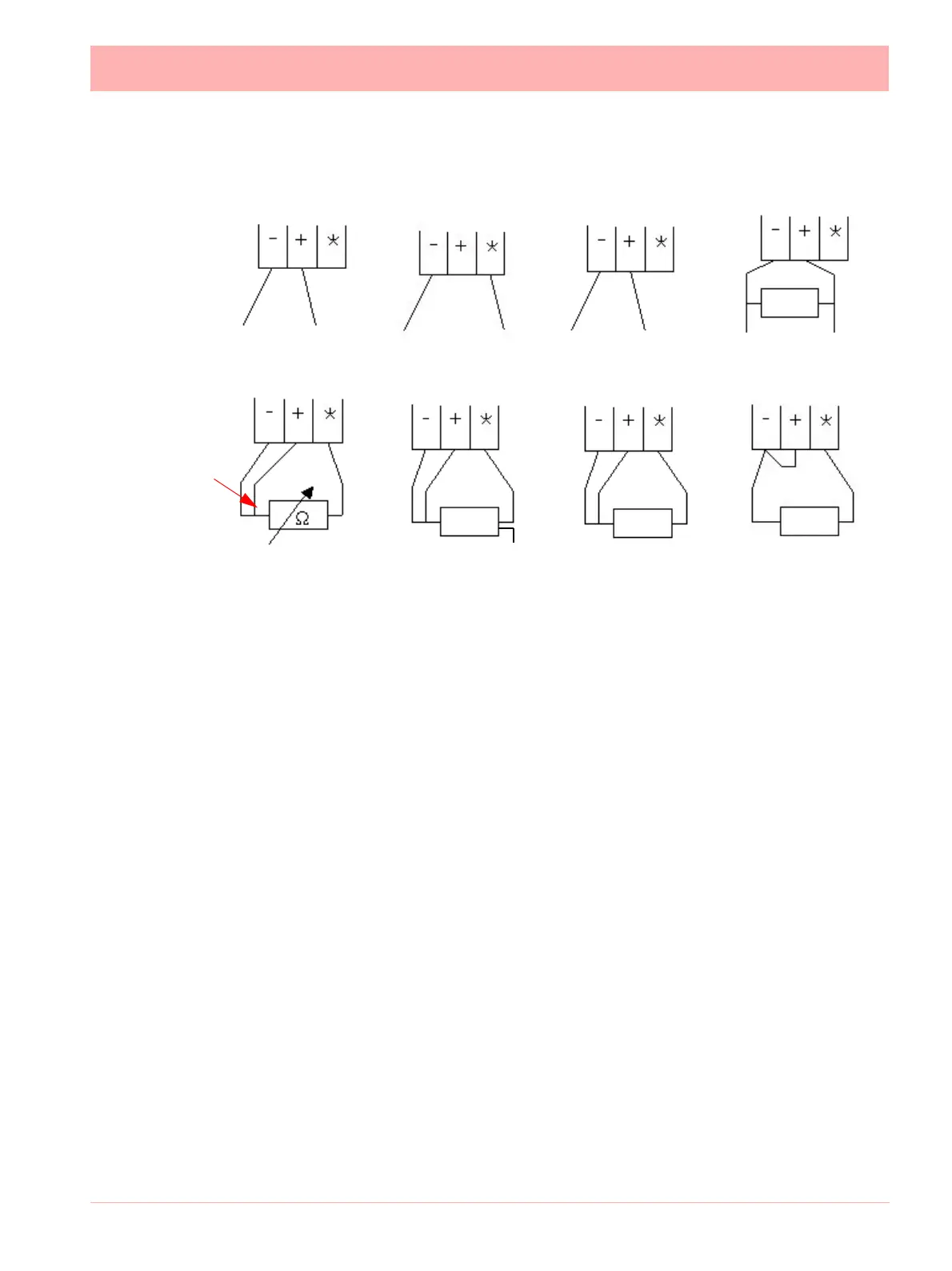
-ve
+ve
Current
10R
Ohms
R/T
R/T
2-wire R/T
3-wire R/T
-ve +ve
Figure 2.7 Input signal wiring
+ve optional
connection
Passive Burnout
Thermocouples
Volts/mV
-ve +ve
-ve
+ve
Active Burnout
Thermocouples
R/T
4-wire R/T
 Loading...