43-TV-25-30 Iss.6 GLO Aug 07 UK 303
Appendix J: Function Codes and Memory Maps
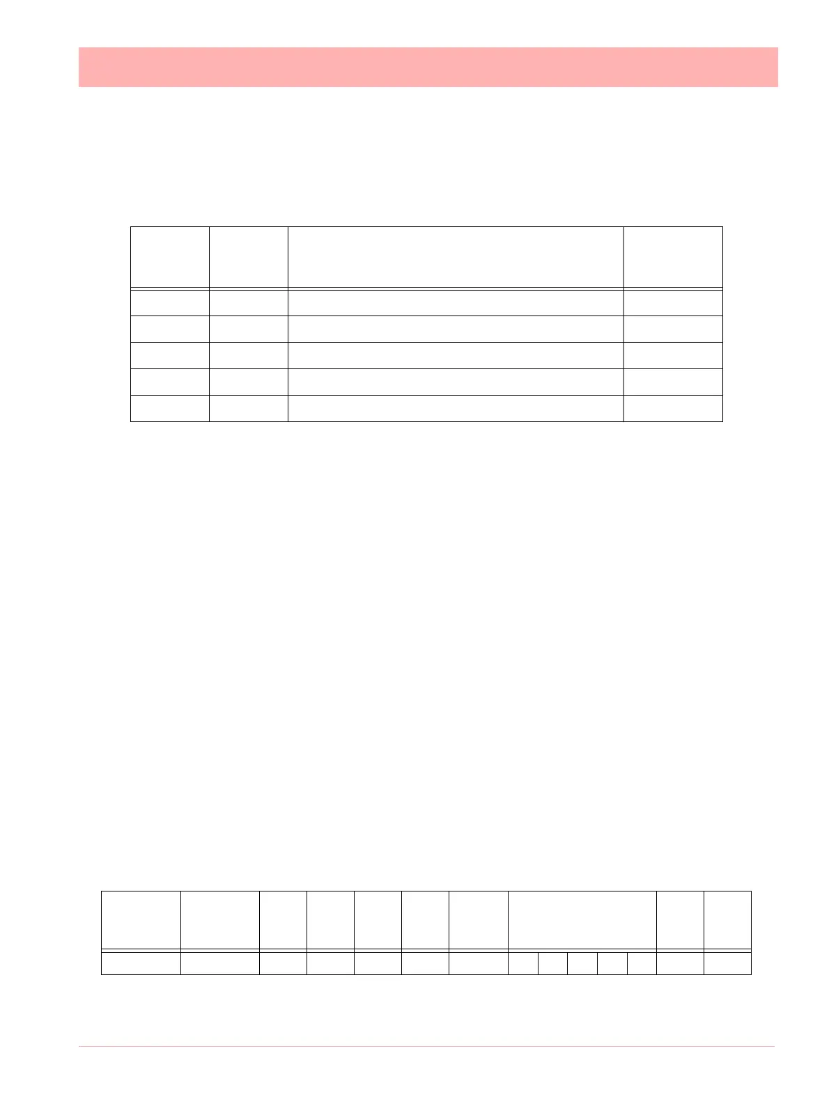
Modbus Memory Map Supplement:
Refer to document ModbusSerial Communications User manual, 51-52-25-66P, 04/06.
* Communications Inputs can be set by using Modbus function code 16
NOTE: Some Modbus masters may require an offset of 1 for example instead of entering
1800 enter 1801.
Totalisers
Totaliser values in engineering units, 4 byte IEEE floats using 2 Modbus registers per
reading.
Input Text message
This facility allows a text message to be passed to the recorder to be annotated on the
chart and added to the message log. The maximum length of the message is 32 bytes of
ASCII characters, which need not be null-terminated.
It operates by utilising modbus function code 16 (0x10), Preset Multiple registers, and the
unique address 0x0004 in the modbus global register map (Table A-1)
The modbus message format follows that shown in section 3.7 of the document cited.
The Start Address will be 00 04, and the Byte Count of the number of bytes in the follow-
ing text message. As 2 modbus registers are used to pass an address to function 16, the
Number of Addresses has to be back calculated from the required Byte Count to give the
lowest integer such that (Number of Addresses) * 2
= Byte Count. For example if Byte
Count = 4, then Number of Addresses = 2, but if Byte Count = 5, Number of Addresses =
3.
As an example, to send the 5-character message Start to a slave address 02 the com-
plete message would be:
The response follows the normal response for function code 16 given in section 3.7, and
so to the above message the response would be: 02 10 00 04 00 03 CRC CRC
Start
Address
(Hex)
End
Address
(Hex)
Description
See
Appendix
51-52-25-66P
1800 185F Analogue Input Value (48 inputs max.) A.5
1880 18BF Communications Inputs (32 comms values max.)* A.6
2400 24BF Extended Comms Inputs (96 comms values max.)* A.6
18C0 197F Pen Values (96 pens max.) A.7
1B00 1B7F Totalisers (64 totalisers max.) A.9
Slave
Address
Function
Code
Start
Addr.
High
Start
Addr.
Low
No
Addr.
High
No
Addr.
Lo
Byte
Count
Data CRC CRC
02 10 00 04 00 03 05 53 74 61 72 74 CRC CRC
 Loading...