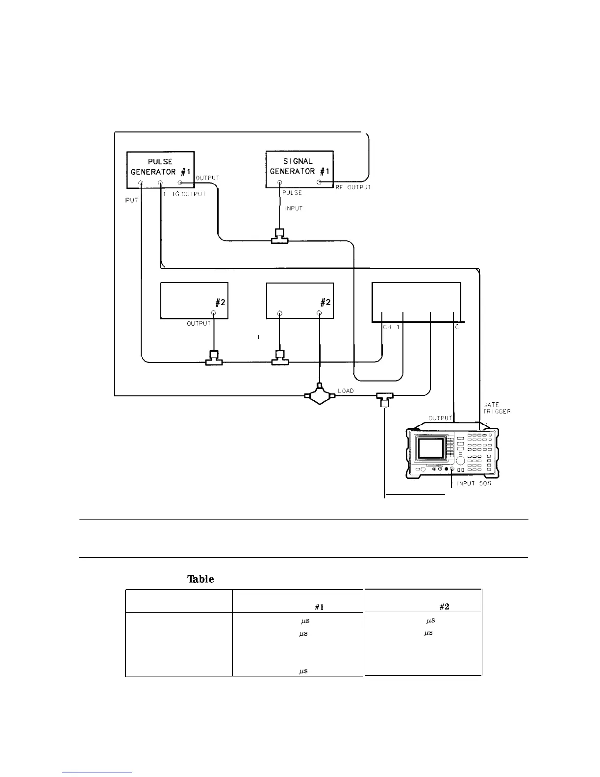
The following example demonstrates the rules for setting up a time-gated measurement. In this
example, we are using two signal generators to generate two signals at the same frequency
(50 MHz). The pulse generators “space” (interleave) the signals in time as well as pulse
modulate the signals.
L
EYT
IPUT
1
R
IG
OUTPUl
MODULATION
PULSE
SIGNAL
GENERATOR
#2
GENERATOR
#2
Q
0
0
PULSE
RF
MODULATION
OUTPUT
1
NPUT
OSCILLOSCOPE
CH
1
CH 2
CH 3
C
REFLECTED
I,
-
SOURCE
/
DIRECTIONAL
BRIDGE
GATE
J
H 4
;ATE
rRlGGER
NPUT
Figure 4-21. Test Setup for Option 105
Note
Be sure that the input impedance for the oscilloscope channels is set to 1 MO.
‘Ihble
4-2. Pulse Generator Test Setup Settings
Setting
Period
Width
Trigger
Voltage (peak-to-peak)
Trigger delay
Pulse
Generator
#l
280
ps
50
/a
Positive edge of square wave
5v
85
ps
Pulse
Generator
#2
280
/Is
50
us
Not applicable
5v
None
Making Measurements 4-27

 Loading...


