Using a Spectrum Analyzer with a Tracking Generator
The procedure below describes how to use the built-in tracking generator system of the
HP 85913 Option 010 spectrum analyzer to measure the rejection of a low-pass filter which
is a type of transmission measurement. Illustrated in this example are the functions in the
tracking-generator menu, such as adjusting the tracking-generator output power, source
calibration, and normalization. Conducting a reflection measurement is similar and is covered
in “Making Reflection Calibration Measurements”.
or Application Note
150-7,
for more information.
Refer to the HP Spectrum Analyzer Seminar,
Stepping through the Measurement
There are four basic steps in performing a stimulus-response measurement, whether it be
a transmission or reflection measurement: set up the spectrum analyzer settings, calibrate,
normalize, and measure.
1. If necessary, perform the self-calibration routine for the tracking generator described in
“Performing the Tracking Generator Self-Calibration Routine” in Chapter 2.
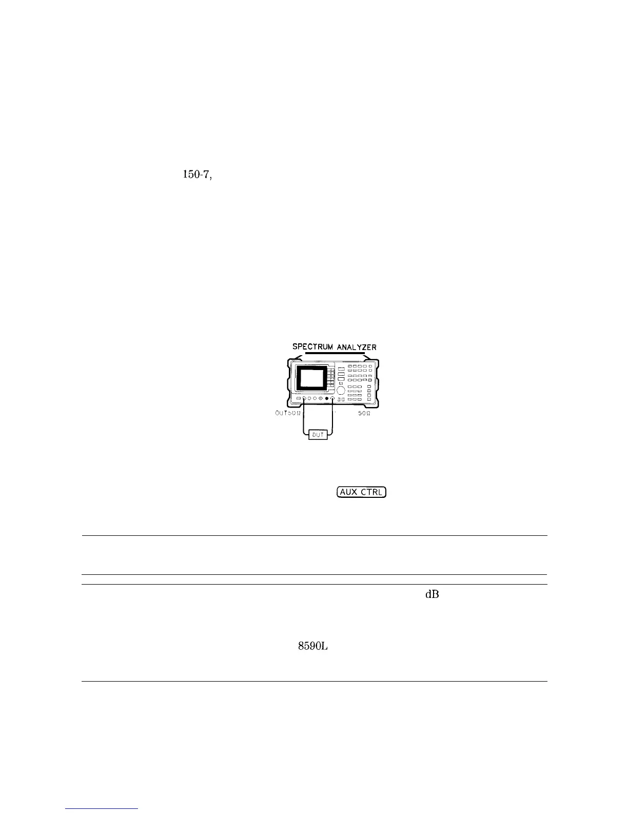
2. To measure the rejection of a low-pass filter, connect the equipment as shown in Figure 4-4.
This example uses a filter with a cut-off frequency of 300 MHz as the DUT.
SPECTRUM
ANALYZER
RF
OlJi
INPUT
SOS7
Figure 4-4. Transmission Measurement Test Setup
3. Activate the tracking generator menu by pressing
(%ZiK]
and Track Gen . To activate
the tracking-generator power level, press SRC PWR ON OFF until ON is underlined
(see Figure 4-5).
Caution
Excessive signal input may damage the DUT. Do not exceed the maximum
power that the device under test can tolerate.
Note
To reduce ripples caused by source return loss, use 10
dB
or greater tracking
generator output attenuation. Tracking generator output attenuation is
normally a function of the source power selected. However, the output
attenuation may be controlled by using SRC ATN AUTO MAN . (There is no
output attenuation in the HP
85901,
with Option 010 or Option 011.) Refer to
specifications and characteristics in your calibration guide for more information
on the relationship between source power and source attenuation.
4-8 Making Measurements

 Loading...


