Setting the Gate Delay and Gate Length Properly, When NOT Using the
Gate Utility
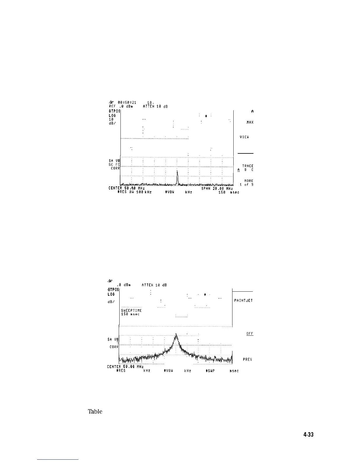
If the gate delay and gate length are not set properly, you may not be viewing an accurate
representation of a signal. For example, If the gate does not occur during the RF pulsed signal,
the amplitude of the signal displayed on the spectrum analyzer is lower than the actual signal
(see Figure 4-28).
$7,
08;5d0B;21
OCT
18,
1998
ATTEN
10 dB
CLEAR
GTPOS
. . . . . . . . . . . . . . . . . . . . . . . . . . . . . . . . . . . . . . . . . . . . . . . . . . . . . . . . . . . . . . . . . . . . . . . . . . . . . . . . . . . . . . . . . . . . . . . . . . .
WRITE
A
LOG
,I:
g,
..
I
:
',
flAX
HOLD A
'.
.'
:
~~~.....,.~,......,,,,,,.....~~~~.,.,,,,,.....,,,~~~~~~.~..:
. . . . . . . . . . . . . . . . . . . .
VIEW A
..
:
,'
BLANK A
:
~il;i
*,‘i:i
lRES
iW
188
kHz
#UBW 100 kHz
RSWP 15~ msec RT
Figure 4-28. Gate Not Occurring During the Pulse
The time gate is implemented after the resolution bandwidth filtering and before the video
filtering. The displayed signal is a result of the decay time for the resolution bandwidth filters
and is not an accurate representation of the input signal.
If the gate occurs at the beginning of the RF pulse signal or at the end of the RF pulse signal,
the signal displayed on the spectrum analyzer can be attenuated or contain transient signals
caused by the spectrum analyzer (see Figure 4-29). If this happens, decrease the gate length
and change the gate delay to place the gate output during the signal.
&
REF
.0
dBm
RTTEN
10
dB
B&W
G
T
p
o
$
. . . . . . . . . . . . . . . . . . . . . . . . . . . . . . . . . . . . . . . . . . . . . . . . . . . . . . . . . . . . . . . . . . . .
LOG
:
:
PRINTER
.*.
10
dB/
"
:
"'
..
PAINTJET
.'
'....
PRINTER
SWEiPTIME
150 msec
:
,.........:
PRINTER
ADDRESS
:
PRT NENU
.'.'
ON
OFF
:
I
SC FC
PRINTER
SETUP
F”:
,‘W
PREV
MENU
CENTER
qCL.RCI
MU,
--.._
111._
SPAN 20.00 MHz
lRES BW 100 kHz
#UBW 108 kHz
HSWP 150 msec RT
Figure 4-29. Gate is Occurring at the Beginning of the Pulse
In Figure 4-29, the peak amplitude has not been reached, and the transient response of the
resolution bandwidth filters adds noise.
Table 4-4 and
lhble
4-5 provide the recommended initial spectrum analyzer settings when
measuring a signal without signal delay.
Making Measurements
4.33

 Loading...


