Resolving Signals of Equal Amplitude Using the Resolution
Bandwidth Function
In responding to a continuous-wave signal, a swept-tuned spectrum analyzer traces out the
shape of the spectrum analyzer intermediate frequency (IF) filters. As we change the filter
bandwidth, we change the width of the displayed response. If a wide filter is used and two
equal-amplitude input signals are close enough in frequency, then the two signals appear as
one. Thus, signal resolution is determined by the IF filters inside the spectrum analyzer.
The resolution bandwidth (RES SW) function selects an IF filter setting for a measurement.
Resolution bandwidth is defined as the 3
dB
bandwidth of the filter. The 3
dB
bandwidth tells
us how close together equal amplitude signals can be and still be distinguished from each other.
Generally, to resolve two signals of equal amplitude, the resolution bandwidth must be less
than or equal to the frequency separation of the two signals. If the bandwidth is equal to the
separation a dip of approximately 3
dB
is seen between the peaks of the two equal signals, and
it is clear that more than one signal is present. See Figure 3-2.
In order to keep the spectrum analyzer calibrated, sweep time is automatically set to a
value that is inversely proportional to the square of the resolution bandwidth. So, if the
resolution bandwidth is reduced by a factor of 10, the sweep time is increased by a factor of
100 when sweep time and bandwidth settings are coupled. (Sweep time is proportional to
1/BW2.)
For fastest measurement times, use the widest resolution bandwidth that still permits
discrimination of all desired signals. The spectrum analyzer allows you to select from 30 Hz to
3 MHz resolution bandwidth in a 1, 3, 10 sequence, plus 5 MHz, for maximum measurement
flexibility.
Example: Resolve two signals of equal amplitude with a frequency separation of 100
kHz.
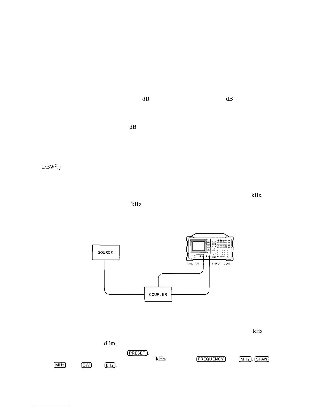
1. To obtain two signals with a 100 kHz separation, connect the calibration signal and a signal
source to the spectrum analyzer input as shown in Figure 3-l. (If available, two sources can
be used.)
Figure 3-l. Set-Up for Obtaining Two Signals
2. If you are using the 300 MHz calibration signal, set the frequency of the source 100 kHz
greater than the calibration signal (that is, 300.1 MHz). The amplitude of both signals should
be approximately -20 dBm.
3. On the spectrum analyzer, press
Cm].
Set the center frequency to 300 MHz, the span to
2 MHz, and the resolution bandwidth to 300 kHz by pressing
(FREQUENCY]
300 [$iK),
@Ei@
2
IFvlHz_),
then
Isw]
300
(kHz).
A single signal peak is visible.
3-2 Making Basic Measurements

 Loading...


