34
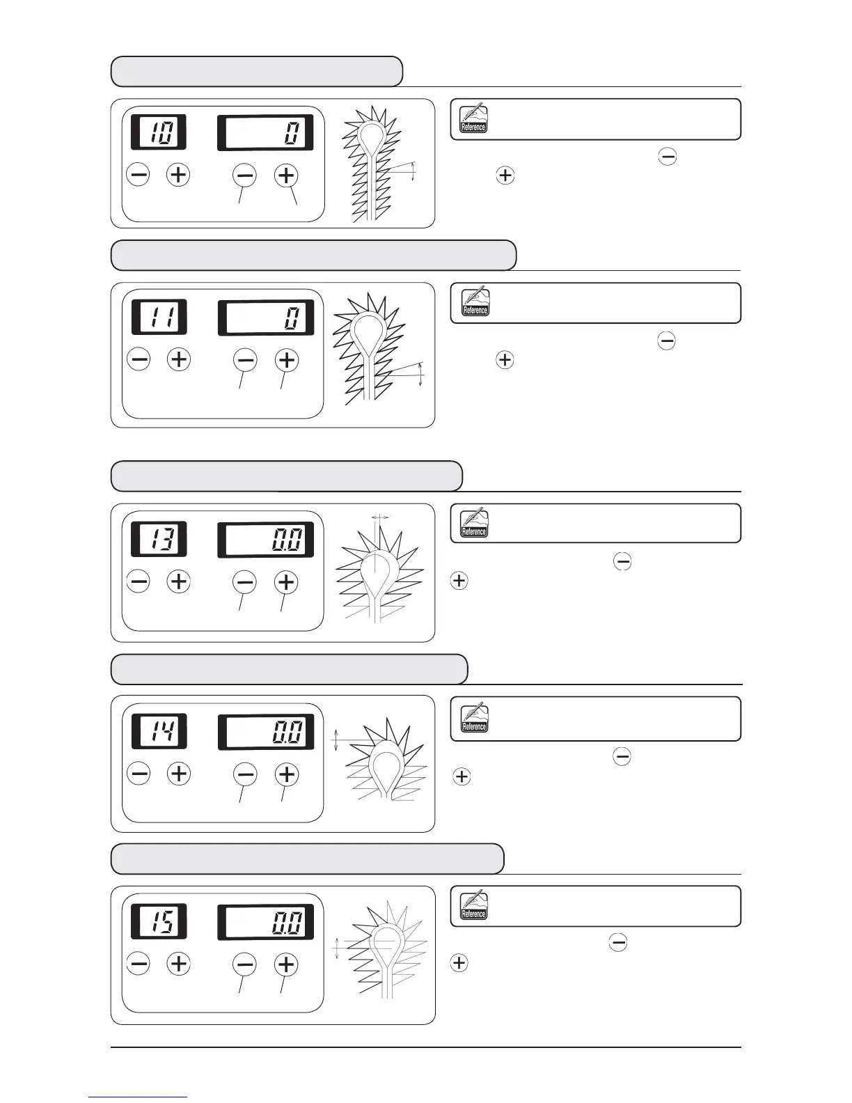
(3) Compensation of turning
Turning angle of the eyelet section and of
the parallel section can be adjusted.
Set the turning angle with [RIGHT ] key
or
[RIGHT ] key
.
Setting can be performed
−
14˚ to 14˚.
(5) Eyelet crosswise compensation
Position on the top of eyelet can be
moved to the right- or left-hand.
Set the position with [RIGHT ] key
or [RIGHT
] key
.
Setting can be performed
−
0.6 to 0.6 mm in the
increments of 0.1 mm.
(6) Eyelet lengthwise compensation
Shape on the top of eyelet can be expanded
or contracted in the longitudinal direction.
Set the position with [RIGHT ] key
or [RIGHT
] key
.
Setting can be performed
−
0.2 to 0.6 mm in the
increments of 0.1 mm.
(7) Left eyelet lengthwise compensation
Length of the left side on the top of eyelet
can be adjusted.
Set the length with [RIGHT ] key
or [RIGHT
] key
.
Setting can be performed
−
0.2 to 0.6 mm in the
increments of 0.1 mm.
(4) Parallel section turning compensation
Turning angle of parallel section and
bottom of eyelet can be adjusted.
Set the turning angle with [RIGHT ] key
or
[RIGHT ] key
.
When the turning compensation of the
aforementioned (3) is performed, the
compensation is performed in the form of adding
the compensation value of turning of (3).
Setting range is
−
14
≦
compensation of turning
+
compensation of turning at parallel section
≦
14.
+
−
−
+
+
−
−
+
+
−
 Loading...