10.4.3 Close the printhead housing
1. Clean, if necessary, the printhead housing (5).
2. Place the printhead cover (7) and place the lock screws (6).
3. Connect the mains power cable and switch on the control unit.
10.4.4 Replacing the printhead PCB [X18, X18si, X18+]
CAUTION:
Always ensure anti-static precautions are observed when handling the Printhead or Printhead PCB
(PIB) or it might get damaged, see subsection 10.4.1
1. Open the printhead housing. Refer to subsection 10.4.2.
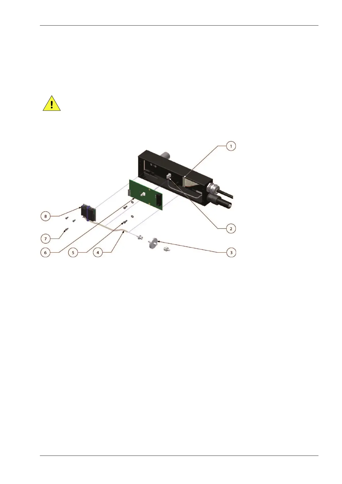
Fig. 10.2 Replace printhead parts [X18, X18si, X18+]
2. Disconnect the data cable (1) and low ink connector (2) from the PIB.
3. Loosen the two PIB screws (5).
4. Take the PIB (6) out of the printhead housing. Pull the PIB gently but firmly off the printhead
connector.
5. Take the new PIB out of the anti-static bag.
6. Push the PIB gently but firmly in the printhead connector. Make sure the PIB is exactly in line with
the printhead and aligned with the printhead connector.
7. Fasten the PIB screws.
8. Connect the data cable and low ink connector to the PIB.
9. Close the printhead housing. Refer to subsection 10.4.3.
10. Prime excessive air from the system.
11. The printer is now ready to print.
 Loading...