3.5 User interface
The user interface on the control unit consists of a capacitive touch panel displaying the menu structure of
operator menus.
The touch panel consists of a capacitive touch screen and a TFT panel. The screen can also be operated with
gloves on (supplied with the ink). A stylus for capacitive touch screens can also be used if required.
3.5.1 Menu structure
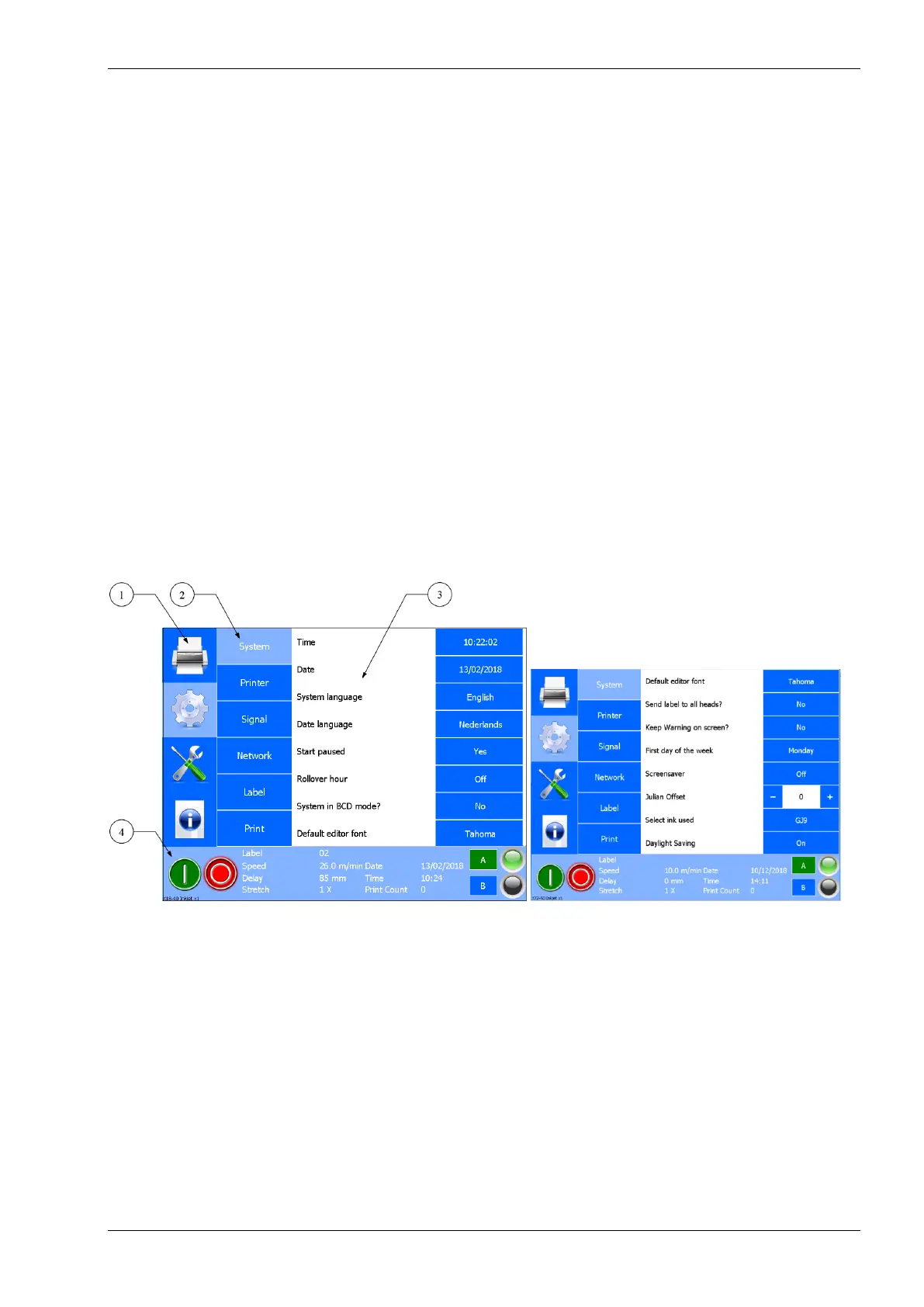
The screen is divided in four parts, see Fig. 3.3. Section 1 shows the 4 main menu options:
1. Print (label selection and label management).
2. Settings (all printer and interface settings).
3. Service and Diagnostics (service and diagnostic functions).
4. Information (system information).
Section 2 shows the submenus available when the Printer setting icon is selected. When another main menu
option is selected in section 1, different submenus will be shown.
Section 3 shows the menu items available in the submenu selected in section 2. Depending on the submenu
selected the contents of this section will change. It’s possible that not all the functions are displayed on the
screen. To access the remaining functions, simply drag the screen upwards
Section 4 shows the status of the printer, the Start (I) and Pause (0) button and the coding units connected to
the control unit (A and B).
Fig. 3.3 Screen layout
3.5.2 LED indicators on control unit
The status screen of the control unit shows a LED indicator indicating if the printhead(s) connected to the
control unit is (are) ready to print (green) or not (orange). E.g. when there is not enough ink present in the
inksystem the LED indicator will turn orange and a low ink message will be shown on screen.
1. Section 1, main menu items
2. Section 2, submenu items
3. Section 3, menu items of the
submenu and preview area
4. Section 4, status
 Loading...