3 PRINT PROCESS DESCRIPTION
3.1 Print cycle
The purpose of the printer is to print a label on a substrate. A label is digital data and is stored in the
memory of the control unit. The control unit converts the label into a bitmap. The printhead receives this
bitmap pixel-column by pixel-column and uses it to fire ink dots on the substrate. The ink drop fire rate is
controlled by pulses, which are generated by either an internal clock or an external encoder. The vertical dot
resolution is 185 dpi for the X18 series and 180DPI for the X54 and X72 series. The horizontal dot resolution
depends on the speed setting. At the correct speed, by parameter setting or use of an encoder, the horizontal
print resolution is 185 dpi for the X18-series and 180 dpi for the X54 and X72 series.
The print cycle is initiated with a signal, called ‘print request’, and generally generated by a photocell, which
detects the product or special mark on the substrate. When a print has been made, the bitmap will be
updated, if necessary, for label items such as time, date and number. When this is done, the busy output is
deactivated and the printer is ready for receiving the next print request.
3.2 Printhead
The heart of the GraphicJet printer is the printhead. The printhead uses patented digital drop on demand
(DOD) piezo ink jet printing technology. It is seen in a range of industrial printing applications, including
coding and marking, as it is a versatile technology able to print on a wide variety of substrates.
This printing technology uses a ceramic material that deforms when an electric field is applied to it. This
deformation is harnessed in order to eject ink from each of the printhead's ink channels in a highly
controlled and repeatable manner. Each pixel on the substrate is either covered with ink or not - a binary
choice.
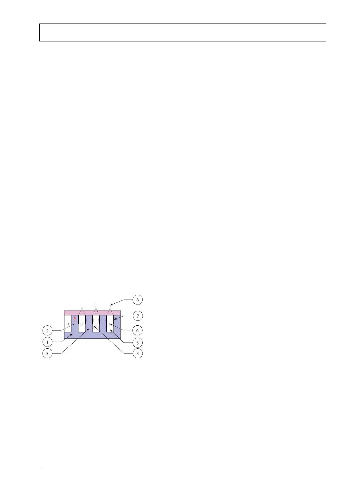
In simplified overview, the technology consists of a series of ink chambers packed together into a printhead,
divided by shared chamber walls with an electrode attached to each side (Fig. 3.1).
Fig. 3.1 Piezo printhead technology
The piezo material is made of lead zirconate titanate (PZT). This ferroelectric ceramics becomes piezo-electric
when poled.
When a voltage is applied across this material the material distorts or bends. This phenomenon is
implemented in the printhead by machining rows of parallel channels into a PZT block. An electrode is then
placed onto the sides of the channel walls allowing a voltage to be applied across it. The way in which the
wall bends due to the applied voltage is known as 'shear mode'. Two channels share the wall, and hence the
term shared wall.
 Loading...