6.3.4 Printhead rotation [X54] [X72]
A rotation of the printhead means that the ink level related to the printhead will change. For proper
functioning of the printhead, the ink level must be kept between the specifications as explained in section
3.3. A quick and simple way to achieve this is the use of the graphs as described in this chapter.
The dimensions and graphs are based on the type of clamps and shafts as used in the standard support set.
For every axial or radial rotation angle of the printhead, the ink reservoir must be set at a specific height. For
easy measurement, the height between the top of the ink reservoir and top of the pole clamp is used. It is
important that the support pole is levelled (use the built-in spirit leveller of the ink reservoir).
The top of the pole clamp is called datum-A and the top of the ink reservoir is called datum-B. The height-
AB dimension is negative if datum-A is above datum-B, see Fig. 6.10.
To set the proper ink level of the coding unit for an axial or radial printhead rotation:
1. Rotate the printhead housing so that the plane of the front-plate is positioned parallel to the
substrate and perpendicular to the direction of the product.
2. Position the printhead housing at the desired print position. Datum-A is now fixed.
3. Determine with the figures in subsection 6.3.5 and 6.3.6 the type of printhead rotation, either radial
or axial
4. Measure or set the rotation angle (
) is 0° when the printhead housing is levelled.
5. Look in the rotation graph, Fig. 6.13 or Fig. 6.16, which height-AB (
) according to the graph-curves. Which graph-curve is chosen depends on the
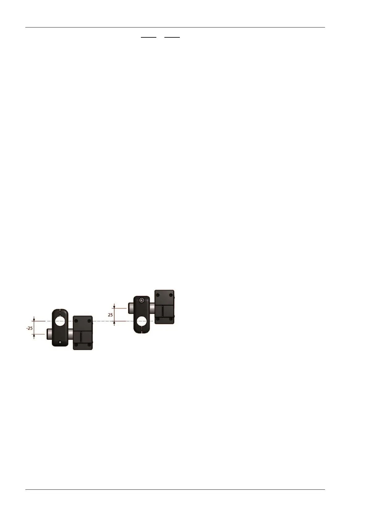
mounting of the printhead clamp in Fig. 6.9, either clamp down or clamp up (
).
6. Position the ink reservoir so that the distance between datum-A and datum-B is equal to the found
height-AB. Use, if necessary, extra clamps, poles or shafts.
7. Level the ink reservoir.
8. Check the height-AB.
A B
Fig. 6.9 Printhead clamp mounting options
Printhead clamp down
6.3.5 Radial printhead rotation
The figures
Fig. 6.10 to Fig. 6.12 shows some examples with a radial rotation of the printhead. To change the position of
the ink reservoir, refer to subsection 6.3.2.
 Loading...