ENGINE MECHANICAL SERVICE MANUAL NUMBER 22
Page 3A-96 90-860074--1 FEBRUARY 2002
Testing - Measuring Lobe Lift
1. Remove all rocker arm assemblies.
2. Secure dial indicator 91-58222A1 to head so indicator plunger rests inside push rod cup.
3. Turn crankshaft so camshaft lobe is at the bottom of its travel and zero dial indicator.
4. Turn crankshaft two complete revolutions while reading dial indicator. Refer to
specifications.
5. Measure all lobes of camshaft in the same manner.
IMPORTANT: Camshaft replacement will be necessary if lobe dimensions are less
than 0.05 mm (.0019 in.) of the values indicated in the specification charts.
Removal
1. Turn crankshaft to cylinder number 1 TDC of its compression stroke.
2. Remove:
a. Timing Gear Cover
b. Fuel Pump
IMPORTANT: Place rocker arm assemblies, push rods and lifters in a rack for
reassembly in their original locations.
c. Valve Push Rods
d. Retainers and Roller Lifters
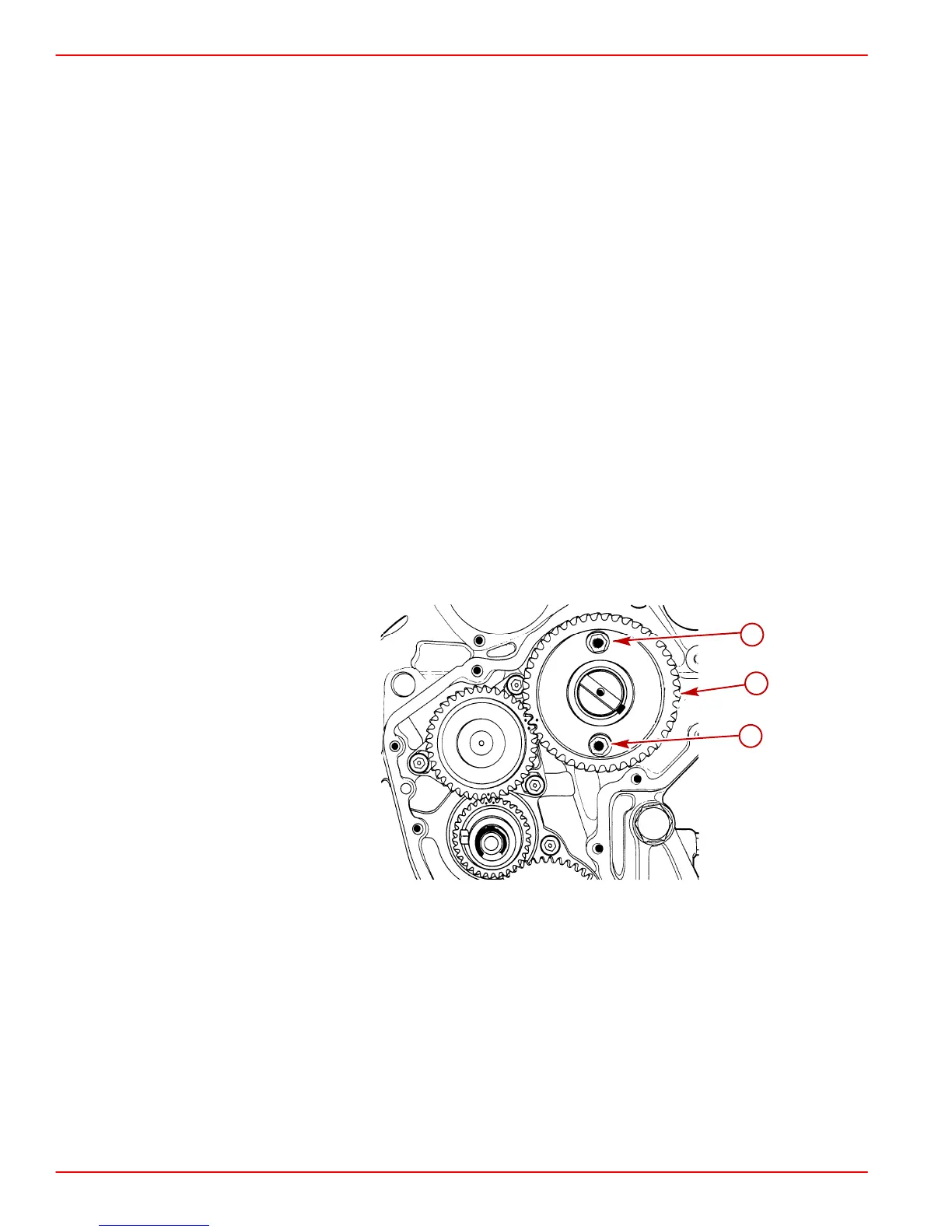
3. Remove camshaft thrust plate mounting screws and lockwashers.
70289
a
b
b
a-Camshaft Gear
b-Camshaft Thrust Plate Mounting Screw with Lockwasher
4. Carefully withdraw the camshaft. Take care not to damage the camshaft bearings.
 Loading...


