ZF / HURTH TRASNSMISSIONS SERVICE MANUAL NUMBER 22
Page 8A-16 90-860074--1 FEBRUARY 2002
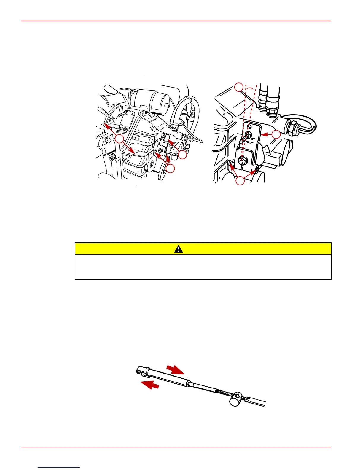
Shift Cable Installation And Adjustment
IMPORTANT: Ensure that shift lever is positioned approximately 10 degrees aft of
vertical as shown when in the neutral detent position. Also, ensure that the distance
between studs in the following is set at 181 mm (7-1/8 in.). If necessary, loosen clamp-
ing bolt and position lever so that dimension “c” is as shown when in the neutral det-
ent position, and retighten clamping bolt.
72958
a
c
d
50228
a
b
d
10
o
Typical ZF / Hurth Transmission Shown
a-Shift Lever
b-Shift Lever In Neutral Detent
c-Dimension Between Studs - 181 mm (7-1/8 In.)
d-Clamping Bolt
CAUTION
Avoid severe transmission damage. All ZF / Hurth Transmissions require Standard
Left-Hand rotation engines. NEVER connect a ZF / Hurth Transmission to a
Right-Hand rotation engine.
IMPORTANT: Transmission propeller rotation is determined by the shift cable instal-
lation in the remote control.
• Right-hand Propeller Rotation - Control cable will have to be installed in remote
control so that cable end will move in direction “A” when shift handle is placed in the
forward position.
• Left-hand Propeller Rotation - Control cable will have to be installed in remote control
so that cable end will move in direction “B” when shift handle is placed in the forward
position.
23242
A
B
 Loading...


