EDI DIAGNOSIS
SERVICE MANUAL NUMBER 22
90-860074--1 FEBRUARY 2002 Page 5E-113
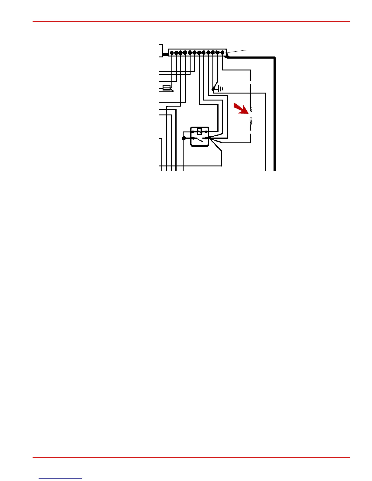
Idle Speed Setting Circuit
77611
RED/ORN
RED/ORN
12
An electrical circuit, using two RED/ORANGE wires inside the electrical box, has been
added to allow for a 100 rpm increase in the base idle speed signal from the ECM. This is
called the Idle Speed Setting Circuit.
Locate the RED/ORANGE wire male and female bullet connector ends. One wire end is
from terminal 12 of the ECM / Fuel System Harness connector and the other is from terminal
87 of the Main Relay. When the wires are connected the engine idle speed should be 700
rpm. If the wires are disconnected the idle speed should be 600 rpm.
Determine the best idle speed for the power package and application. Set the idle speed
circuit accordingly.
INSPECTION
1. Visually inspect connectors for corrosion, if wires are connected.
2. Visually inspect for terminals that may have backed out of the harnesses.
CLEANING
1. Clean connectors with a suitable tool or solvent, if wires are connected.
INSTALLATION
1. Connect the RED/ORANGE wire male and female bullet connector ends and the engine
idle speed should be 700 rpm.
NOTE: If the RED/ORANGE wire bullet connectors are disconnected the idle speed should
be 600 rpm.
 Loading...


