EDI DIAGNOSIS SERVICE MANUAL NUMBER 22
Page 5E-40 90-860074--1 FEBRUARY 2002
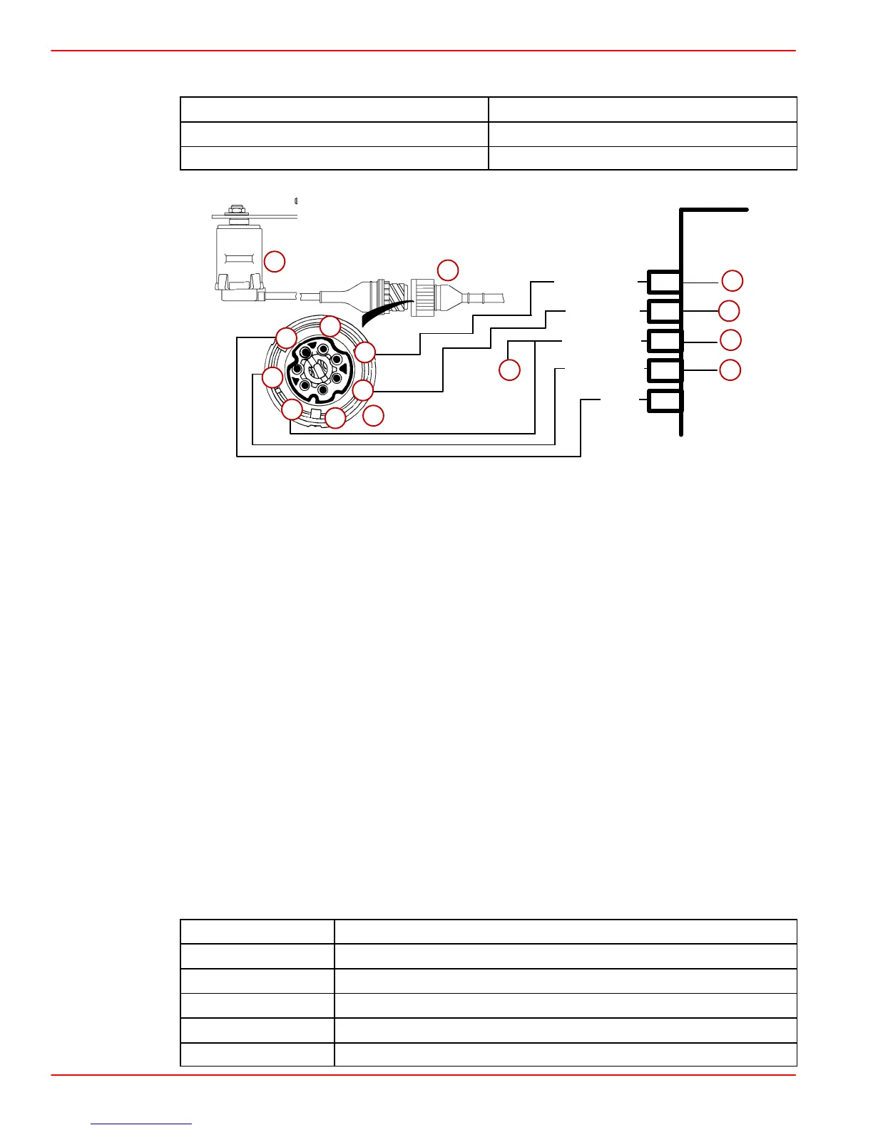
TP (Throttle Position) Sensor / Low Idle Switch
Scan Code: P1515
Blink Code: 1144
Malfunction Indicator Lamp: ON
ECM
57
15
ORN/WHT
55
65
75565
1
BLU/WHT
BRN/RED
BLK
PNK/YEL
a
b
c
d
e
fg
b
1
2
3
4
7
6
5
a-TP Sensor
b-Harness Connector
c-TP Sensor Signal
d-5 Volt Reference Signal
e-Sensor Ground (–)
f-Battery Supply Voltage
g-To MAP/IAT Sensor
CIRCUIT DESCRIPTION:
The TP (Throttle Position) sensor translates throttle position into a voltage signal. The TP
sensor is basically a linear potentiometer. The ECM supplies 5 volts to the sensor and
processes a returning voltage signal for operation of the fuel timing solenoid valve. The TP
output voltage will vary through the range from idle to WOT. Also at closed throttle the Low
Idle Switch (sometimes referred to as LGS) is activated. This confirms to the ECM that the
TP is at the closed throttle position. As the throttle position changes the output increases,
so that at WOT, the output voltage should be near 4.5 volts. By monitoring the output voltage
from the TP sensor, the ECM can determine fuel delivery based on the throttle position
(operator demand).
If the TP circuit is open, the ECM will set a Scan Code P1515. If the TP circuit is shorted,
the ECM will think the vessel is at WOT, and this code will be set. A problem in any of the
TP circuits (e. g. Low Idle Switch) will set this same code. Once this trouble code is set, the
ECM will use a default value for TP signal.
CKT PIN
NAME
15 TP Sensor Signal
57 5 Volt Reference Signal
55 Sensor Ground (–)
65 Low Idle Switch (LGS)
1 ECM / Battery Ground (–)
 Loading...


