V Series Operating Instructions 4 - 21
Mechanical Functions V Hub
4.5.8 Connecting the V Hub to the V 12/V 21
Connect the V Hub to the V 12/V 21 using the interface cable shown in FIGURE 4-35. Mount the V
Hub on a rolling stand (shown in FIGURE 4-20 on page 4-13) or to a wall mount (shown in FIGURE 4-
29 on page 4-18).
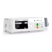
FIGURE 4-35 V Hub Interface Cable
NOTE: The interface cable red and white connectors are not interchangeable
and must be inserted into the correct outlet. If they are not, the
connector will not insert.
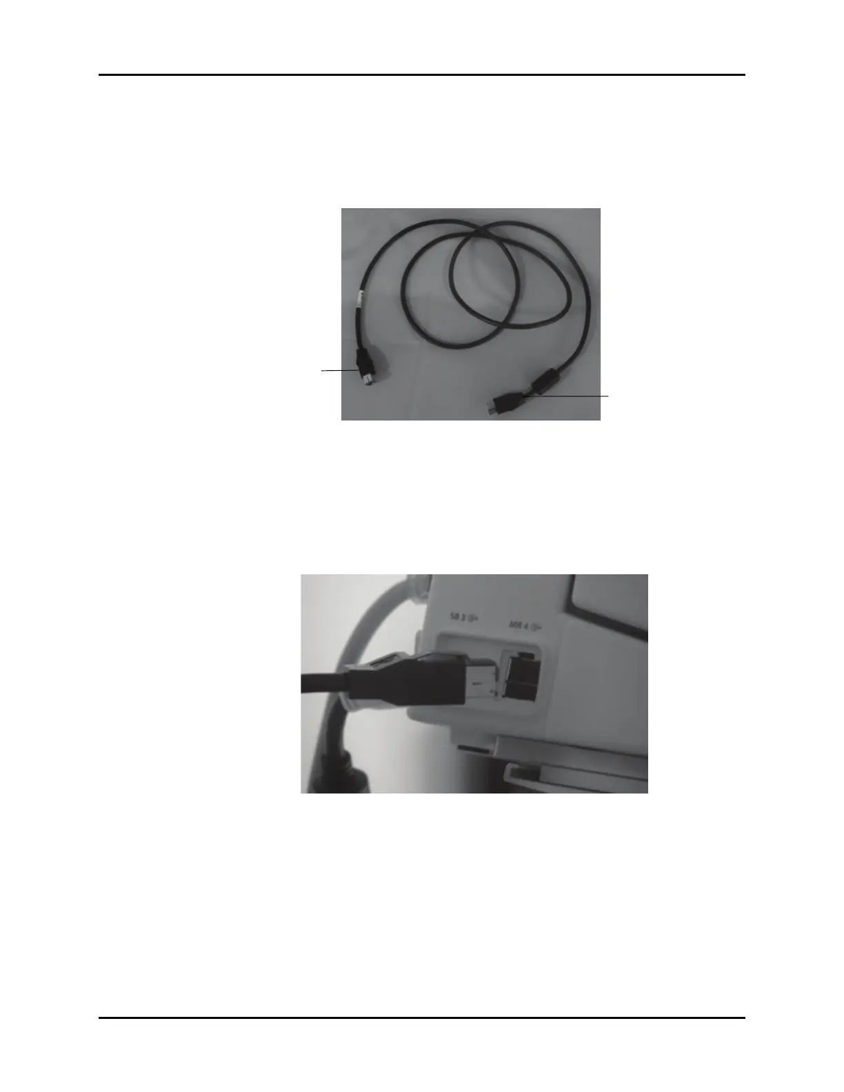
1. Insert the red connector of the interface cable into an available MR port (there are four MR ports)
in the V Dock (shown in FIGURE 4-36).
FIGURE 4-36 V Dock Connector
2. Insert the white connector of the interface cable into the MR X (where X represents the port
number) port in the V Hub (shown in FIGURE 4-37).
V Dock Connector
(Red)
V Hub Connector
(White)
 Loading...