5.40
9924880 Rev 2- 1/10/2014 - 2013 / 2014 RANGER XP 900 - 2014 RANGER XP 900 / CREW 900 Service Manual
© Copyright Polaris Sales Inc.
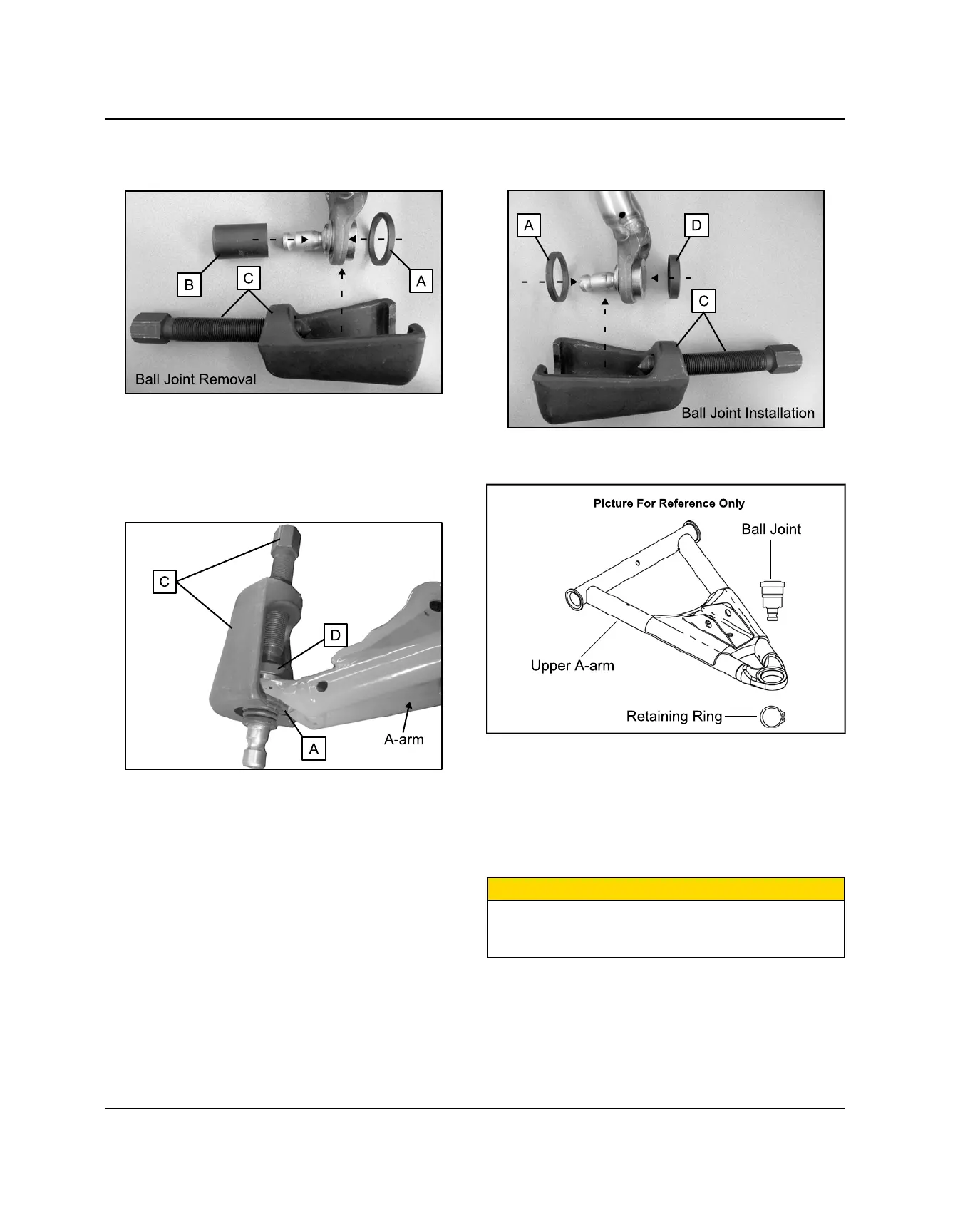
5. Tighten the Press Asm. screw and fully remove the
ball joint from the A-arm.
BALL JOINT INSTALLATION
1. By hand, install the NEW ball joint into the A-arm.
2. Position the Installation Adapter (D) over the face of
the ball joint.
3. Position the Spacer (A) over the shaft of the ball joint
so it is against the A-arm.
4. Install the Press Asm. (C) onto the A-arm to engage
the Installation Adapter and Spacer.
5. Tighten the Press Asm. screw and fully install the
ball joint into the arm.
6. After the new ball joint is fully installed into the A-
arm, install a new retaining ring.
7. Repeat the ball joint service procedure for any
additional A-arm ball joint replacements.
8. Insert upper / lower A-arm ball joint end into the
bearing carrier. Install new pinch bolts and nuts.
Torque to specification.
9. If needed, install new brake caliper mounting bolts
and torque to specification.
CAUTION
New bolts have a pre-applied locking agent which is
destroyed upon removal. Always use new brake caliper
mounting bolts upon assembly.
BODY / STEERING / SUSPENSION
 Loading...