7.8
9924880 Rev 2- 1/10/2014 - 2013 / 2014 RANGER XP 900 - 2014 RANGER XP 900 / CREW 900 Service Manual
© Copyright Polaris Sales Inc.
FRONT PROPSHAFT
REMOVAL / INSTALLATION
1. Remove the front bumper (see Chapter 5).
2. Elevate and safely support vehicle under the frame.
The use of a vehicle hoist is recommended for this
procedure.
CAUTION
Serious injury may result if machine tips or falls. Be
sure machine is secure before beginning this service
procedure. Wear eye protection when removing
bearings and seals.
3. Remove the front gearcase from the vehicle (see
"Front Gearcase Removal" provided in this chapter).
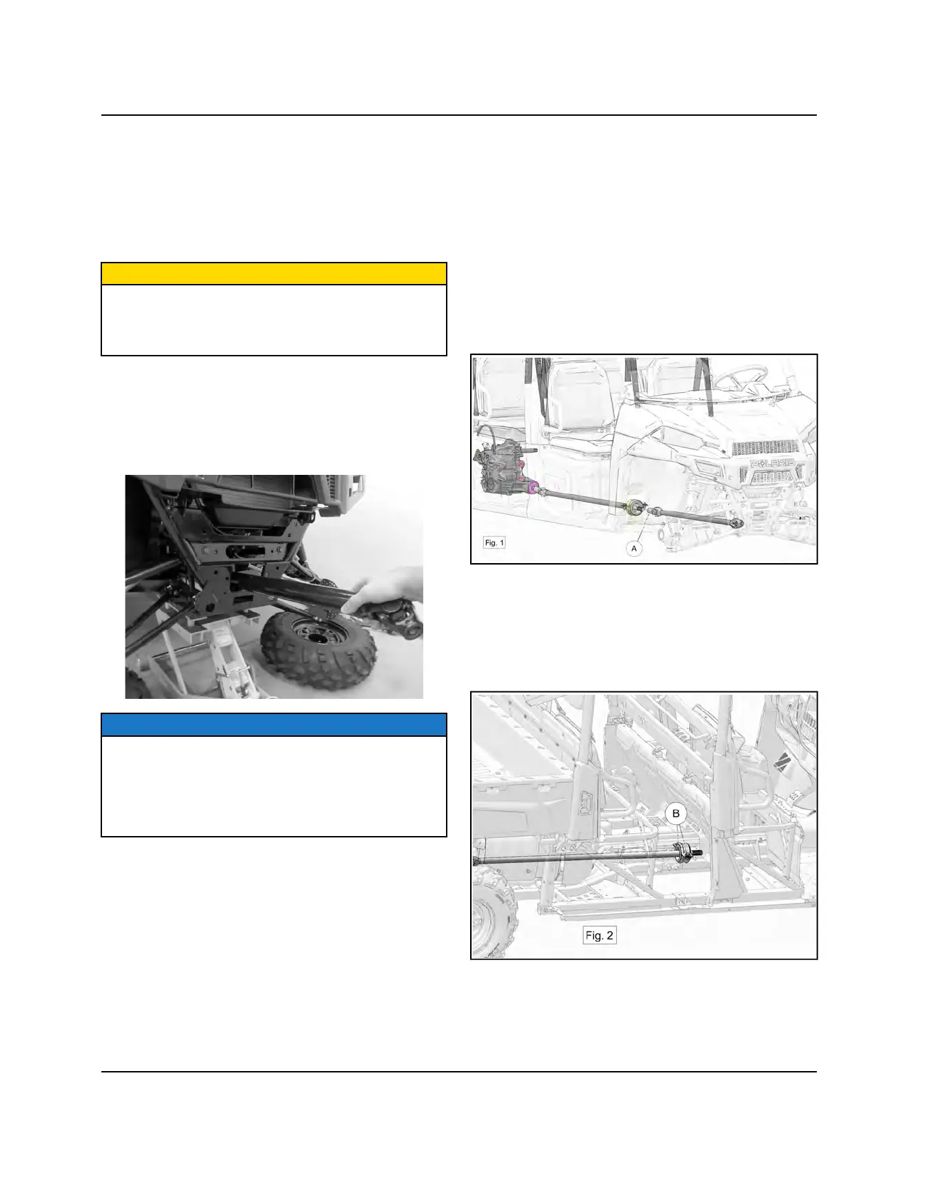
4. Pull the front propshaft towards the front of the
vehicle until the splines on the rear yoke disengage
from the transmission snorkel shaft. Remove the
propshaft out the front of the vehicle as shown.
NOTE
If the propshaft does not fully disengage from the
transmission snorkel shaft, remove the skid plate to
access the front engine mount support. Remove the (2)
driver's side engine mount nuts. Doing so will allow you
to lift up on the engine to get more clearance between
the propshaft and the steel skid plate.
5. Reverse this procedure to reinstall the front
propshaft. Use a NEW roll pin upon installation.
REMOVAL / INSTALLATION - CREW
Removal
1. Remove the front bumper (see Chapter 5).
2. Elevate and safely support vehicle under frame. The
use of a vehicle lift is recommended for this
procedure.
3. Remove the front gearcase (see “Front Gearcase
Removal”).
4. Separate the front section of the propshaft assembly
from the splines in front of the flex bearing A (Fig. 1).
5. Remove the front skid plate.
6. Remove the rear skid plate.
7. Remove rear floor (see Rear Floor - CREW in
Chapter 5).
8. Remove the (2) fasteners (B) Fig. 2 securing the flex
bearing to the frame.
9. Slide the rear section of the propshaft assembly from
the transmission output shaft.
10.Remove the propshaft assembly through the rear
floor opening.
FINAL DRIVE
 Loading...