10
9924880 Rev 2- 1/10/2014 - 2013 / 2014 RANGER XP 900 - 2014 RANGER XP 900 / CREW 900 Service Manual
© Copyright Polaris Sales Inc.
10.3
GENERAL INFORMATION
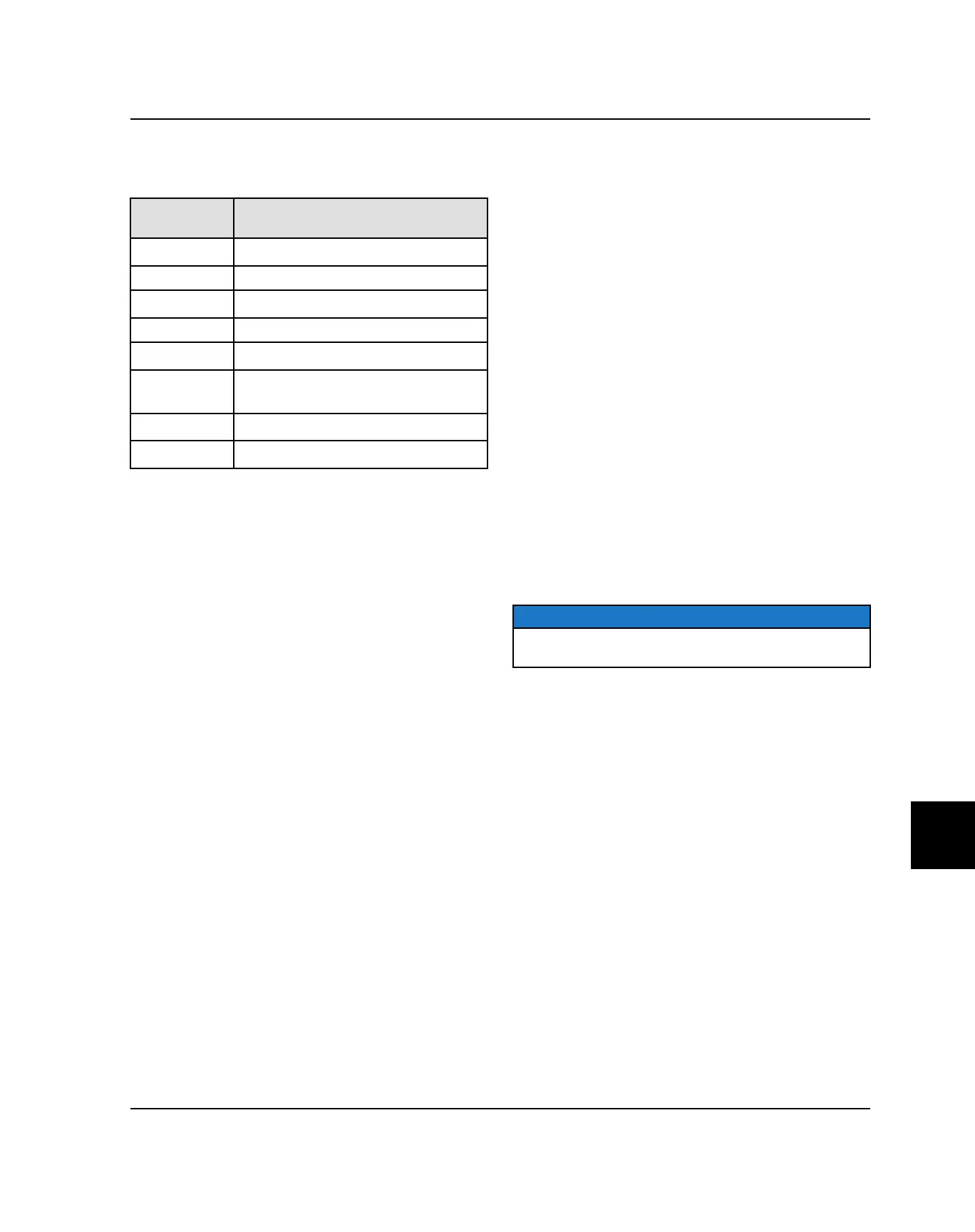
SPECIAL TOOLS
PART
NUMBER
TOOL DESCRIPTION
PV-43568
Fluke™ 77 Digital Multimeter
PV-43526 Connector Test Kit
2870630
Timing Light
2460761 Hall Effect Sensor Probe Harness
2871745
Static Timing Light Harness
PU-50296
Battery Conductance Analyzer
(MDX-610P)
PU-49466
Relay Bypass
- Digital Wrench® (see Chapter 4)
Bosch Automotive Service Solutions:
1-800-345-2233 or http://polaris.service-solutions.com/
ELECTRICAL SERVICE NOTES
Keep the following notes in mind when diagnosing an
electrical problem:
• Refer to wiring diagram for stator and electrical
component resistance specifications.
• When measuring resistance of a component that has a
resistance value under 10 Ohms, remember to
subtract meter lead resistance from the reading.
Connect the leads together and record the resistance.
The resistance of the component is equal to tested
value minus the lead resistance.
• Become familiar with the operation of your meter. Be
sure leads are in the proper jack for the test being
performed (i.e. 10A jack for current readings). Refer to
the Owner’s Manual included with your meter for more
information.
• Voltage, amperage, and resistance values included in
this manual are obtained with a Fluke™ 77 Digital
Multimeter (PV-43568). This meter is used when
diagnosing electrical problems. Readings obtained
with other meters may differ.
• Pay attention to the prefix on the multimeter reading
(K, M, etc.) and the position of the decimal point.
• For resistance readings, isolate the component to be
tested. Disconnect it from the wiring harness or power
supply.
COMPONENTS UNDER HOOD
The following components can be accessed under the
hood.
• Voltage Regulator (in front of radiator)
• Terminal Block
• Headlight Connectors
COMPONENTS BEHIND DASH PANEL
The following components can be accessed with the
upper dash panel removed.
• Instrument Cluster (Speedometer)
• AWD/2WD/TURF Switch
• Headlight Switch
• 12 VDC Accessory Power Points
• Ignition Key Switch
COMPONENTS UNDER PASSENGER SEAT
BASE
The following components can be accessed with the
passenger seat base removed.
• Battery*
• Battery Cables*
• Starter Solenoid*
• Relays*
• Fuses*
• Digital Wrench ® Diagnostic Connector*
• ECU*
• Speed Key Accessory (if installed)
NOTE
*Components are located under rear passenger seat
base on 2014 RANGER CREW 900
ELECTRICAL
 Loading...