7
9924880 Rev 2- 1/10/2014 - 2013 / 2014 RANGER XP 900 - 2014 RANGER XP 900 / CREW 900 Service Manual
© Copyright Polaris Sales Inc.
7.5
BEARING CARRIER INSTALLATION
1. Install the end of the drive shaft through the backside
of the bearing carrier.
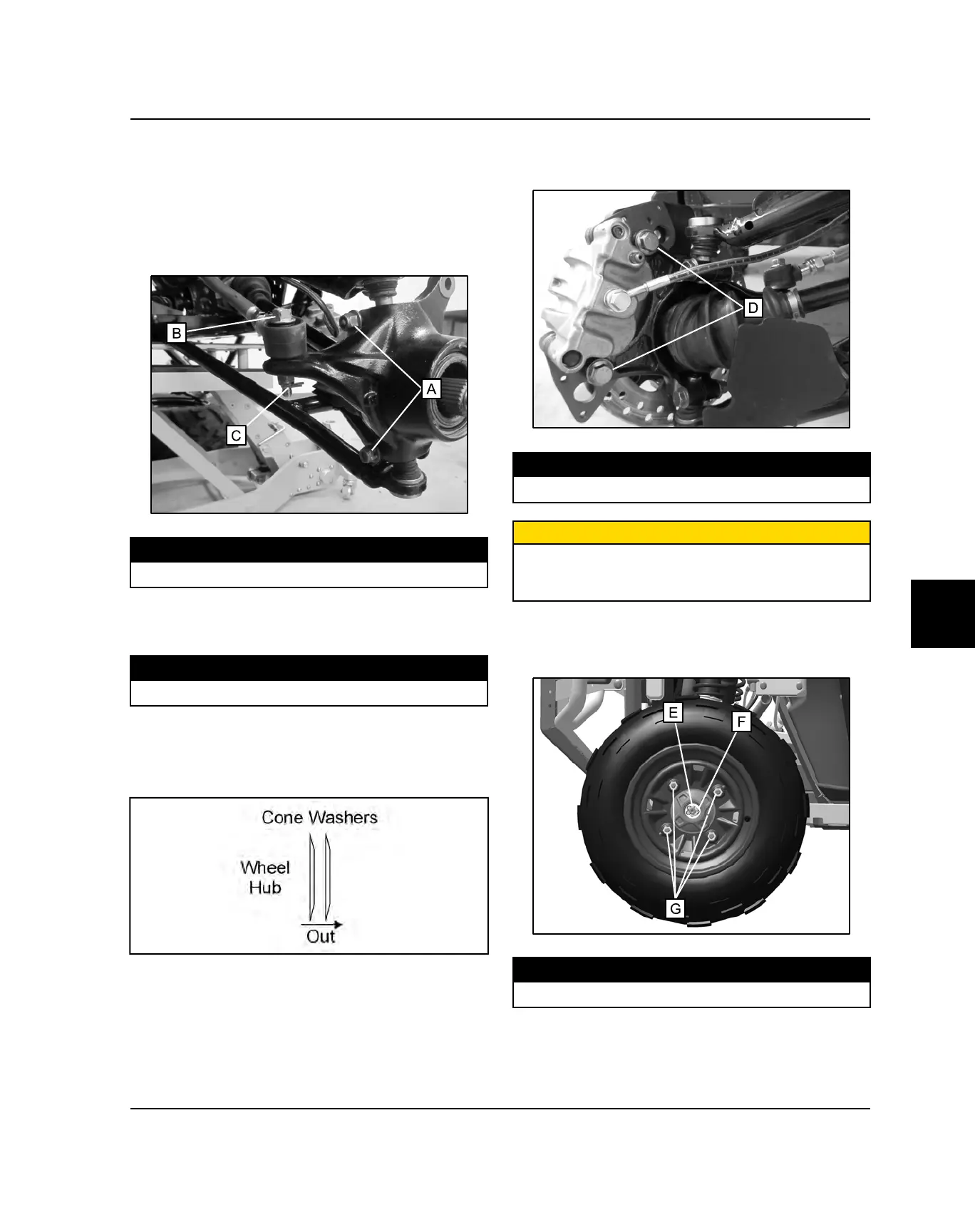
2. Install the upper and lower ball joint ends into the
front bearing carrier.
3. Install pinch bolts (A) and torque to specification.
TORQUE
Ball Joint Pinch Bolts:42 ft-lbs (57 Nm)
4. Install the steering tie rod end onto the front bearing
carrier and torque the fastener (B) to specification.
Install a NEW cotter pin (C)
TORQUE
Tie Rod End Fastener:40 ft-lbs (54 Nm)
5. Apply grease to the drive shaft splines.
6. Install front wheel hub assembly, cone washers, and
hand tighten the castle nut. Install washers with
domed side out.
7. Install the front brake caliper. Install the mounting
bolts (D) and torque to specification.
TORQUE
Front Caliper Mounting Bolts:30 ft-lbs (41 Nm)
CAUTION
New bolts have a pre-applied locking agent which is
destroyed upon removal. Always use new brake caliper
mounting bolts upon assembly.
8. Torque wheel hub castle nut (E) to specification and
install a NEW cotter pin (F). Tighten nut slightly if
necessary to align holes for the cotter pin.
TORQUE
Front Hub Castle Nut:75 ft-lbs (102 Nm)
FINAL DRIVE
 Loading...