Tool offsets
7.3 Special handling of tool offsets
Job planning
Programming Manual, 07/2010, 6FC5398-2BP40-0BA0
403
7.3.4 Tool length and plane change
Function
When setting data SD42940 $SC_TOOL_LENGTH_CONST is set not equal to zero, then
you can assign the tool length components – such as lengths, wear and basic dimension –
to the geometry axes for turning and grinding tools when changing the plane.
SD42940 $SC_TOOL_LENGTH_CONST
Setting data not equal to zero:
The assignment of tool length components (length, wear and tool base dimension) to
geometry axes does not change when the machining plane is changed (
G17 - G19).
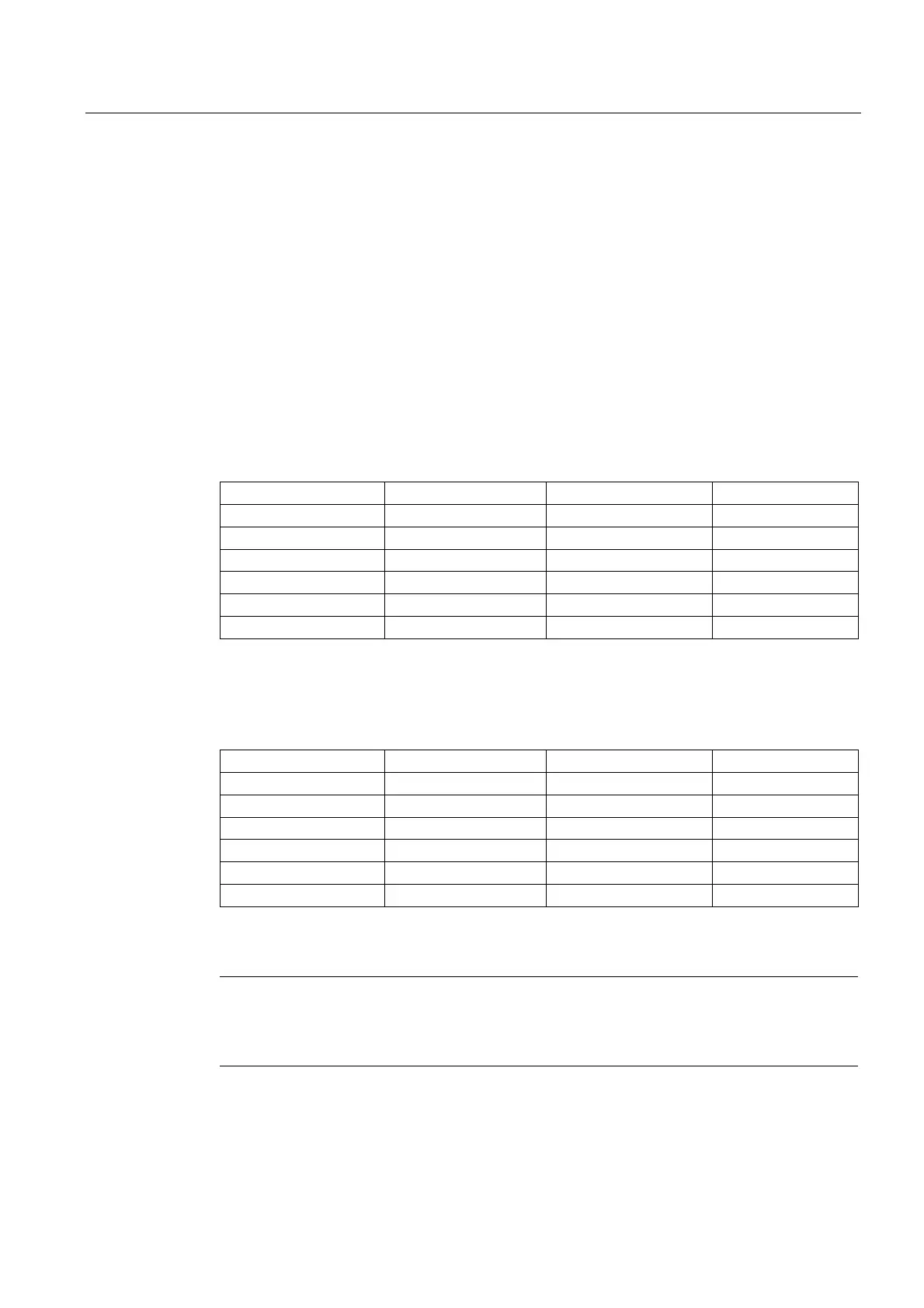
The following table shows the assignment of tool length components to geometry axes for
turning and grinding tools (tool types 400 to 599):
Content Length 1 Length 2 Length 3
17 Y X Z
*) X Z Y
19 Z Y X
-17 X Y Z
-18 Z X Y
-19 Y Z X
*)
Each value not equal to 0, which is not equal to one of the six listed values, is evaluated as
value 18.
The following table shows the assignment of tool length components to geometry axes for all
other tools (tool types < 400 or > 599):
Operating plane Length 1 Length 2 Length 3
*) Z Y X
18 Y X Z
19 X Z Y
-17 Z X Y
-18 Y Z X
-19 X Y Z
*)
Each value not equal to 0, which is not equal to one of the six listed values, is evaluated as
value 17.
Note
For representation in tables, it is assumed that geometry axes up to 3 are designated with X,
Y, Z. The axis order and not the axis identifier determines the assignment between a
compensation and an axis.

 Loading...


