Tool offsets
7.5 Activate 3D tool offsets (CUT3DC..., CUT3DF...)
Job planning
Programming Manual, 07/2010, 6FC5398-2BP40-0BA0
409
7.5 Activate 3D tool offsets (CUT3DC..., CUT3DF...)
7.5.1 Activating 3D tool offsets (CUT3DC, CUT3DF, CUT3DFS, CUT3DFF, ISD)
Function
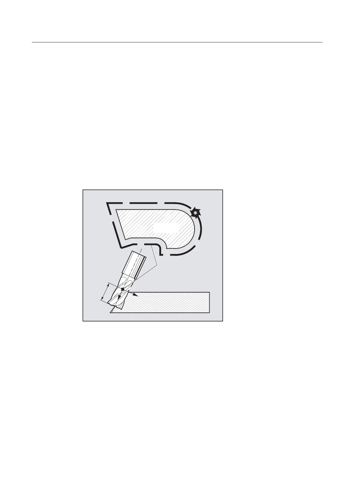
Tool orientation change is taken into account in tool radius compensation for cylindrical tools.
The same programming commands apply to 3D tool radius compensation as to 2D tool
radius compensation. The left/right offset is specified in the direction of motion using
G41/G42.
The approach response is always controlled with
NORM. The 3D radius compensation is only
effective when 5-axis transformation is selected.
3D tool radius compensation is also called 5D tool radius compensation, because in this
case 5 degrees of freedom are available for the orientation of the tool in space.
:RUNSLHFH
FRQWRXU
3DWKRIWKHWRROFHQWHULQ
WKHVDPHGLVWDQFHWRWKH
FRQWRXUHTXLGLVWDQW
5
/
,6'
Difference between 2 1/2 D and 3D tool radius compensation
In 3D tool radius compensation tool orientation can be changed. With the 2 1/2D tool radius
compensation, it is assumed that only a tool with constant orientation is being used.
Syntax
CUT3DC
CUT3DFS
CUT3DFF
CUT3DF
ISD=<value>

 Loading...


