Engineering and remote access
7.6 Cyclic and acyclic data
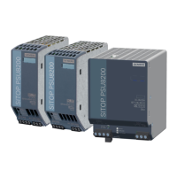
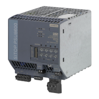
Power supply system SITOP PSU8600
Manual, 09.2018, A5E36758446-5-76
263
9 = FWUpdate A firmware update is
presently being per-
formed.
The basic unit generates
10 = Buffer End End of buffering
Charging state
Charge state of the buffer module Unsigned8
Buffer disabled by
Buffer component was deactivated via the control contact. Unsigned8
LED color Actual LED color. Each
LED is represented by 2
bits:
• Bit0/1: OK
• Bit2-15: unused = 0
Unsigned16
3 LED lit yellow.
LED state Actual display status of
the LEDs. Each LED is
represented by 2 bits:
• Bit0/1: OK
• Bit2-15: unused = 0
Unsigned16
3 LED flashes at 2 Hz
Data sets SITOP UPS8600
Index 1: General (reading/writing)
Maximum charging
power
Maximum charging power
Unsigned8
2 = High (default set-
120 W charging power
Battery test interval Battery test interval 0 = Off The battery module is not
tested.
Unsigned8
1 … 24
Default setting: 6
The connected battery
modules are tested every
Buffer Timer Enable
Specifies whether the timer is activated Unsigned8
Settings for the buffer timer
 Loading...