Description, device design, dimension drawing
2.6 Connections and terminal designations
Power supply system SITOP PSU8600
38 Manual, 09.2018, A5E36758446-5-76
The power cables to the UPS module and to additional battery modules are connected at
power terminals
①. Refer to the diagram in Section "Description of the UPS module
(Page 26)". The data cables to the UPS module and to additional battery modules are
connected at communication terminals
②.
It is not permissible that the "+" and "-" power terminals are connected to the "0V", the 0V
busbar or "GROUND".
Note
Use cables with the same length and the same cross
-section.
Dimension the power cables corresponding to the fuse in the battery module.
The fuse should only be inserted in the fuse holder when comm
issioning the device.
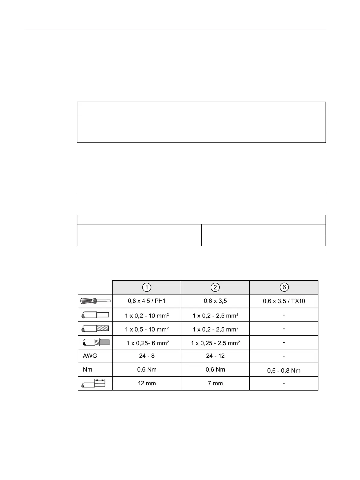
Connections and terminal designations
Power terminals "-" and "+"
Plug-in terminal each with a screw connection
Communication terminals
COM2
, "COM1"
Plug-in terminal each with a screw connection
See the diagram in Section "Description of the battery modules (Page 28)".
Terminal data 6EP4143-8JB00-0XY0, 6EP4145-8GB00-0XY0
 Loading...