EasyManua.ls Logo

Yamaha 01V96 User Manual

Yamaha 01V96
328 pages
To Next Page IconTo Next Page
To Previous Page IconTo Previous Page
Page #154 background imageLoading...
Page #154 background image
154 Chapter 13—Grouping Channels & Linking Parameters
01V96 Version 2—Owner’s Manual
Linking EQ and Compressor Parameters
Follow the steps below to link EQ or compressor parameters for Input Channels or Output
Channels. This function enables you to set EQ or compressor parameters for multiple chan-
nels to the same values simultaneously.
1 Press the DISPLAY ACCESS [PAIR/GROUP] button repeatedly until one of the
following pages appears.
-In EQ page
This page enables you to set EQ links (a–d) for Input Channels 1–32 and ST IN Chan-
nels 1–4.
-Out EQ page
This page enables you to set EQ links (e–h) for Bus Outs (1–8), Aux Outs (1–8) and Ste-
reo Out.

Table of Contents

Other manuals for Yamaha 01V96

Question and Answer IconNeed help?

Do you have a question about the Yamaha 01V96 and is the answer not in the manual?

Yamaha 01V96 Specifications

General IconGeneral
Channels40
Mic Preamps16
Bit Depth24-bit
MIDIYes
EQ Bands4-band Parametric
Aux Sends8
A/D-D/A Conversion24-bit
Effects Processors4
Power SupplyInternal
TypeDigital
Sample Rate44.1 kHz, 48 kHz
EffectsYes
USBNo
Weight33 lbs
Inputs - Other8 digital
Outputs - DigitalAES/EBU, S/PDIF
Computer ConnectivityNo
Sampling Rate44.1 kHz, 48 kHz
Internal Processing32-bit
Dynamic ProcessingGate, Compressor, Limiter
Digital I/OAES/EBU, S/PDIF
Analog I/OXLR, TRS
Outputs - Main2

Summary

Important Safety Instructions

Precautions

Warning

Basic precautions to avoid electrical shock, damage, fire, or other hazards.

Caution

Basic precautions to avoid physical injury or damage to the device or property.

New Functions in 01V96 Version 2

Remote Control

Details on controlling external devices using the 01V96's SELECTED CHANNEL section.

Remote Control

MIDI

2 Control Surface & Rear Panel

Control Surface Overview

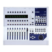
Details on the physical layout and components of the control surface.

Rear Panel Overview

Description of the connectors and sections on the rear panel.

AD Input Section

Monitor Out & Headphones Section

Channel Strip Section

STEREO Section

ST IN Section

DISPLAY ACCESS Section

Display Access Buttons

Details on buttons for accessing various display pages (SCENE, DIO/SETUP, MIDI, etc.).

LAYER Section

Layer Selection Buttons

Details on buttons for selecting Input Channel, Master, or Remote layers.

SELECTED CHANNEL Section

Selected Channel Controls

Details on PAN control and EQ band controls (HIGH, MID, LOW).

SCENE MEMORY Section

USER DEFINED KEYS Section

Data Entry Section

Data Entry Controls

Details on Parameter wheel, ENTER, DEC/INC, and cursor buttons.

Digital I/O Section

Digital I/O Connectors

Details on 2TR IN/OUT DIGITAL, ADAT IN/OUT connectors.

MIDI/Control Section

Power Section

Power Controls

Details on the POWER ON/OFF switch and AC IN connector.

3 Operating Basics

About the Display

Explains the various items indicated on the 01V96's top panel display.

Selecting Display Pages

Display Interface

Display Interface Controls

Details on rotary controls, faders, buttons, and parameter boxes.

Selecting Layers

Layer Selection

Explains the four layers and how they determine control functions.

Selecting Channels

Selecting Fader Modes

Metering

4 Connections and Setup

Configuring an Analog 24-Channel Mixing System

Describes how to connect the 01V96 for an analog mixing system.

Configuring a Recording System with a Hard Disk Recorder

Configuring a Recording System that Uses a DAW (Digital Audio Workstation)

Wordclock Connections and Settings

Specifying the Wordclock Source

10 Input & Output Patching

Patching Input Channels

Explains how input signals are patched to input channels by default.

5 Tutorial

Connections and Setup

Guides through connecting the 01V96 to a digital multitrack recorder for recording.

Initial Track Recording

Setting the Input Levels

Instructions for setting input levels for recording musical instruments.

Pairing Channels

Routing Signals

Adjusting the Monitoring Level

Adjusting the Track Mix Balance

EQ’ing the Input Signals

Compressing Input Channels

Attenuating Input Channels

EQ’ing Input Channels

Panning Input Channels

Routing Input Channels

Viewing Input Channel Settings

Setting the Input Channels from the Control Surface

Input Channel Level and Pan Settings

Explains setting levels and panpots for Input and ST IN channels.

Pairing Input Channels

Pairing Input Channels Using the Display

Naming Input Channels

8 Bus Outs

Setting the Stereo Out and Bus Out 1–8 from the Display

Compressing the Stereo Out and Bus Outs

EQ’ing the Stereo Out and Bus Outs

Routing Bus Out 1–8 Signals to the Stereo Bus

Viewing the Stereo Out and Bus Out Settings

Setting the Stereo Out and Bus Out 1–8 from the Control Surface

Pairing Buses or Aux Sends

Attenuating Output Signals

Naming the Stereo Out and Bus Outs

9 Aux Outs

Aux Out 1–8 Operations

Details on Aux Out parameters and their signal flow.

Setting Aux Out 1–8 from the Display

Comp settings

EQ settings

Viewing Aux Out Settings

Setting Aux Out 1–8 from the Control Surface

Aux Send Level Settings

Instructions on adjusting Aux Send levels from the display.

Aux Send Modes

11 Monitoring

Monitor and Solo Setup

Using the Solo Function

12 Surround Pan

About Surround Pan

Explains the Surround Pan function and its modes (3-1, 5.1, 6.1).

Setting Up and Selecting Surround Pan Modes

13 Grouping Channels & Linking Parameters

Grouping & Linking

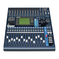
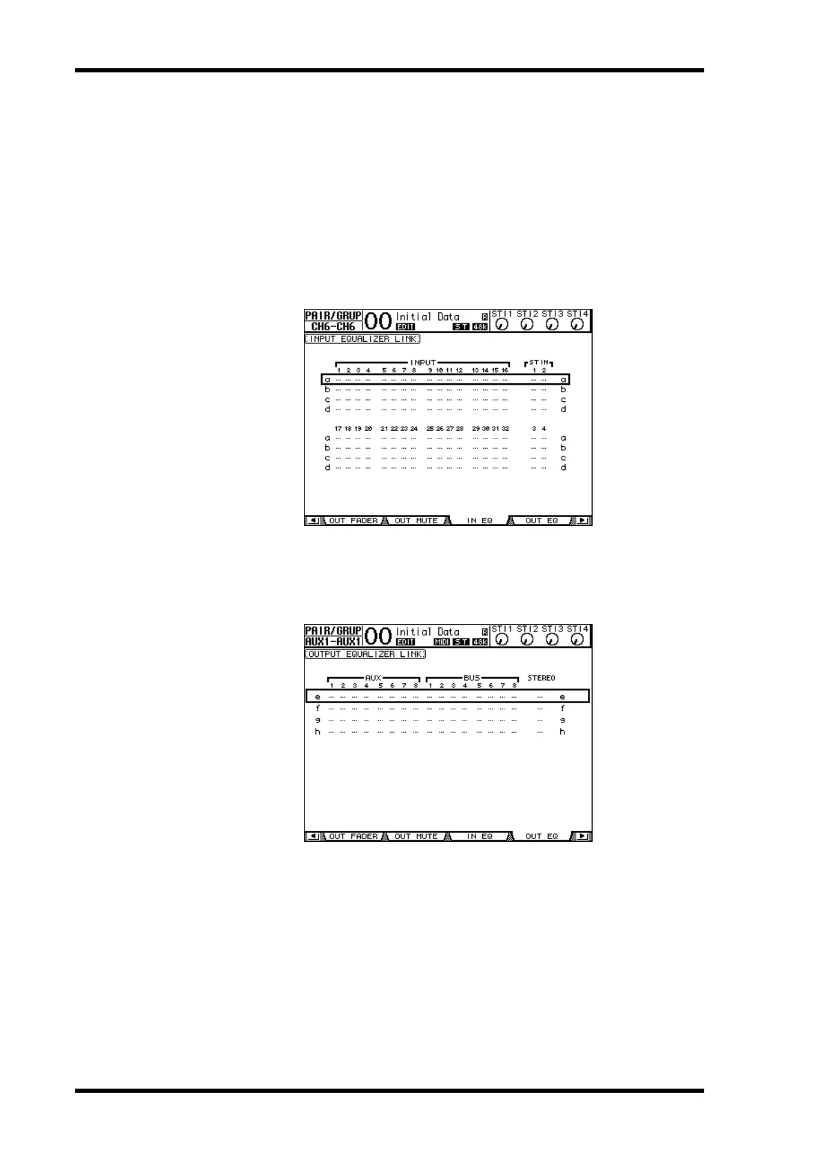
Explains grouping faders, ON buttons, and linking EQ/compressor parameters.

Using Fader Groups and Mute Groups

Using Fader Group Master

Using Mute Group Master

Linking EQ and Compressor Parameters

14 Internal Effects

About the Internal Effects

Overview of the 01V96's four internal multi-effects processors.

Inserting the Internal Effects into Channels

Editing Effects

15 Scene Memories

About Scene Memories

Explains what Scene memories are and how they store mix and effects settings.

What is Stored in a Scene?

Lists the parameter settings that are stored within a Scene.

Storing and Recalling Scenes

Storing and Recalling Scenes Using the SCENE MEMORY Buttons

Instructions on storing and recalling Scenes using the top panel buttons.

Storing and Recalling Scenes Using the Scene Memory Page

Recalling Scenes Safely

Recall Safe Functionality

Details on Global Recall Safe, SAFE, MODE, and RECALL SAFE CHANNEL.

16 Libraries

About the Libraries

Overview of the seven libraries available for storing and recalling settings.

Using Libraries

Channel Library

Details on storing and recalling Input/Output Channel parameter settings.

17 Remote Control

About Remote Function

Explains the Remote function for controlling external DAWs and MIDI devices.

Pro Tools Remote Layer

Connections and Configuring Pro Tools

Instructions for connecting the 01V96 to a computer for Pro Tools control.

Configuring the 01V96

Control Surface Operation

Assigning Plug-ins to Pro Tools Channels

Editing Plug-ins

Nuendo/Cubase SX Remote Layer

Other DAW Remote Layer

MIDI Remote Layer

Using the MIDI Remote Function

Describes how to recall and use factory-preset MIDI Remote settings.

Assigning MIDI Messages to Channel Controls

18 MIDI

MIDI & the 01V96

Overview of MIDI messages supported by the 01V96.

MIDI Port Setup

Selecting a Port for MIDI Message Transfer

Instructions for configuring MIDI ports for message transfer.

Assigning Scenes to Program Changes for Remote Recall

Assigning Parameters to Control Changes for Real-time Control

Parameter Assignment via Control Changes

Instructions on assigning 01V96 parameters to MIDI Control Changes.

19 Other Functions

Changing the Input and Output Channel Names

Instructions on changing default channel names for inputs and outputs.

Changing the Output Channel Names

Setting Preferences

Creating a Custom Layer by Combining Channels (User Assignable Layer)

User Assignable Layer Setup

Instructions on creating a custom layer by combining channels.

Using the Oscillator

Using the User Defined Keys

Assigning Functions to User Defined Keys

Instructions on assigning functions to the USER DEFINED KEYS buttons.

Using Operation Lock

Operation Lock Functionality

Details on enabling/disabling Operation Lock with a password.

Cascading Consoles

Appendix A: Parameter Lists

Appendix B: Specifications

Analog Input Spec

Details the specifications for the analog input connectors.

Analog Output Specs

Details the specifications for the analog output connectors.

Appendix C: MIDI

Initial Parameter to Control Change Table

Lists default assignments of 01V96 parameters to MIDI Control Changes.

Related product manuals