Parameter List
1
1.17 U: Monitors
YASKAWA TOEPYAIGA5002A GA500 DRIVE PROGRAMMING 113
No.
(Hex.)
Name Description MFAO Signal Level
U2-15
(07E0)
SFS Output @ Fault
Shows the output frequency after soft start at the fault that occurred most recently.
Use U1-16 [SFS Output Frequency] to monitor the output frequency after soft start.
Unit: 0.01 Hz
No signal output available
U2-16
(07E1)
q-Axis Current@Fault
Shows the q-Axis current of the motor at the fault that occurred most recently.
Use U6-01 [Iq Secondary Current] to monitor the q-Axis current of the motor.
Unit: 0.1 %
No signal output available
U2-17
(07E2)
d-Axis Current@Fault
Shows the d-Axis current of the motor at the fault that occurred most recently.
Use U6-02 [Id ExcitationCurrent] to monitor the d-Axis current of the motor.
Unit: 0.1%
No signal output available
U2-19
(07E4)
ControlDeviation@Flt
Shows the amount of control axis deviation (Δθ) at the fault that occurred most recently.
Use U6-10 [ContAxisDeviation Δθ] to monitor the actual amount of control axis deviation (Δθ).
Unit: 0.1 °
No signal output available
U2-20
(008E)
Heatsink Temp @Fault
Shows the heatsink temperature at the fault that occurred most recently.
Use U4-08 [Heatsink Temperature] to monitor the temperature of the heatsink.
Unit: 1 °C
No signal output available
U2-21
(1166)
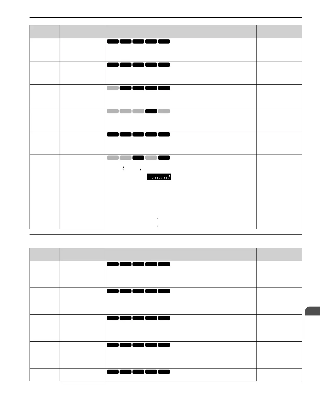
Expert
STPo Detect @ Fault
Monitors conditions to detect STPo [Motor Step-Out Detected] faults. The bit for each condition is
shown as = ON or = OFF.
For example, U2-21 shows when the drive detects excessive current.
bit0 : Excessive current
bit1 : Induced voltage deviation
bit2 : d-axis current deviation
bit3 : Motor lock at startup
bit4 : Acceleration stall continue
bit5 : Acceleration stall repeat
bit6 : Not used (normal value of [ ]).
bit7 : Not used (normal value of [ ]).
No signal output available
◆ U3: Fault History
No.
(Hex.)
Name Description MFAO Signal Level
U3-01
(0090)
1st MostRecent Fault
Shows the fault history of the most recent fault.
Note:
The drive saves this fault history to two types of registers at the same time for the MEMOBUS/
Modbus communications.
No signal output available
U3-02
(0091)
2nd MostRecent Fault
Shows the fault history of the second most recent fault.
Note:
The drive saves this fault history to two types of registers at the same time for the MEMOBUS/
Modbus communications.
No signal output available
U3-03
(0092)
3rd MostRecent Fault
Shows the fault history of the third most recent fault.
Note:
The drive saves this fault history to two types of registers at the same time for the MEMOBUS/
Modbus communications.
No signal output available
U3-04
(0093)
4th MostRecent Fault
Shows the fault history of the fourth most recent fault.
Note:
The drive saves this fault history to two types of registers at the same time for the MEMOBUS/
Modbus communications.
No signal output available
U3-05
(0804)
5th MostRecent Fault
Shows the fault history of the fifth most recent fault.
No signal output available

 Loading...


