
 Loading...
Do you have a question about the YASKAWA GA500 GA50U Series and is the answer not in the manual?
| Type | DC Drive |
|---|---|
| Manufacturer | YASKAWA |
| Dimensions | Varies by model |
| Weight | Varies by model |
| Series | GA50U |
| Control Method | Vector Control, V/f Control |
| Protection Features | Overcurrent, Overvoltage, Undervoltage, Overload, Overtemperature, Short Circuit |
| Communication Interface | EtherNet/IP |
| Ambient Temperature | -10°C to +50°C |
| Humidity | 5% to 95% (non-condensing) |
| Storage Temperature | -20°C to +60°C (-4°F to +140°F) |
Crucial instructions for correct product reception, safety information, and precautions before initial use, including a glossary.
Covers critical safety guidelines, signal words (DANGER, WARNING, CAUTION, NOTICE), and general safety precautions for operating the drive.
Details product warranty, exclusion of liability, and safety warnings for critical applications where failure could cause harm.
Critical safety information and DANGER warnings specific to navigating and using the parameter list.
Explains icons, terms, and how to interpret parameter entries and control mode availability.
Lists and categorizes all drive parameters into logical groups for easier understanding and access.
Covers essential parameters for initial setup, including language, access level, and control method selection.
Details parameters for configuring specific application settings like operation modes, braking, speed search, and energy saving.
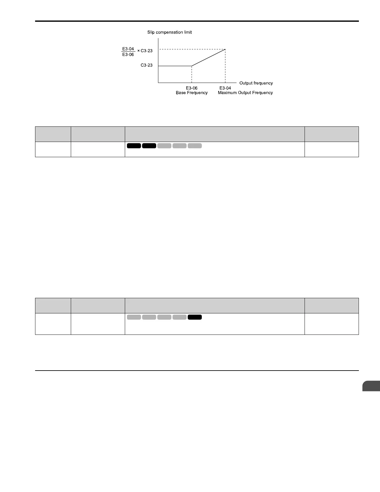
Parameters for optimizing acceleration/deceleration, S-curves, slip compensation, and torque control.
Parameters for setting frequency references, limits, jump frequencies, and up/down commands.
Parameters for defining motor characteristics, including V/f patterns, rated current, voltage, and pole count.
Parameters for configuring communication options, including network settings and fault detection.
Explains how to assign functions to digital and analog input/output terminals for various operations.
Covers essential protection functions like overload, power loss ride-through, stall prevention, and overvoltage.
Parameters for fine-tuning special functions such as hunting prevention, AFR, and EZ tuning for optimal performance.
Settings for customizing keypad display, operation, parameter backup, and maintenance monitors.
Parameters specifically reserved for use with the DriveWorksEZ software.
Parameters related to establishing connections for DriveWorksEZ.
Details on selecting tuning modes and performing auto-tuning for induction and PM motors.
Explains parameters for monitoring drive status, faults, and maintenance information.
Details how default settings vary based on the selected control method (A1-02).
Explains how default settings change based on the selected Motor 2 control mode (E3-01).
Details parameter variations influenced by the V/f pattern selection (E1-03).
Provides default parameter values correlated with specific drive models and duty ratings (ND/HD).
Critical safety information and DANGER warnings relevant to the parameter details section.
Covers essential parameters for initial drive setup, including language, access level, and control method.
Details parameters for configuring specific application settings like operation modes, braking, and speed search.
Parameters for optimizing acceleration/deceleration, S-curves, slip compensation, and torque control.
Parameters for setting frequency references, limits, jump frequencies, and up/down commands.
Parameters for setting up motor characteristics, including V/f patterns, rated values, and auto-tuning.
Parameters for configuring communication options, including network settings and fault detection.
Explains how to assign functions to digital and analog input/output terminals for various operations.
Covers essential protection functions like overload, power loss ride-through, stall prevention, and overvoltage.
Parameters for fine-tuning special functions such as hunting prevention, AFR, and EZ tuning for optimal performance.
Settings for customizing keypad display, operation, parameter backup, and maintenance monitors.
Details on selecting tuning modes and performing auto-tuning for induction and PM motors.
Critical safety information and DANGER warnings relevant to drive startup and testing procedures.
Describes the drive's keypad components, their functions, and operational modes (LOCAL/REMOTE).
Explains how to use the keypad to navigate menus, monitor parameters, and change settings.
Details how to use application presets to automatically configure drive parameters for specific applications.
Provides information on performing auto-tuning for induction and PM motors to set optimal parameters.
Guides users through no-load and actual-load test runs to verify safe and correct drive operation.
Offers guidance on adjusting control parameters like ASR and torque compensation for optimal performance.
A detailed checklist to ensure all necessary checks are performed before and during test runs for safe operation.
Critical safety information and warnings related to the mechanical installation of the drive.
Instructions for safely removing and reattaching the drive's front cover for access.
Details the procedure for removing and reattaching the keypad for installation or replacement.
Critical safety information and warnings regarding electrical installation, including shock and fire hazards.
Illustrates standard wiring procedures for connecting the drive, motor, and power supply.
Provides detailed information on correctly wiring the control circuit, including terminal blocks and MFDI/MFDO settings.
Explains how to configure and connect various control I/O signals, including pulse train, analog inputs, and outputs.
Guides users on connecting the drive to a PC via USB for software monitoring and parameter management.
Instructions for correct product reception, safety information, glossary, and trademark acknowledgments.
Covers critical safety guidelines, hazard identification, and general precautions for safe drive operation.


