5.4 Control I/O Connections
508 YASKAWA TOEPYAIGA5002A GA500 DRIVE PROGRAMMING
5.4 Control I/O Connections
This section gives information about the settings for the listed control circuit I/O signals.
• MFDI (terminals S1 to S7)
• Pulse train output (terminal MP)
• MFAI (terminal A2)
• MFAO (terminal AM)
• MEMOBUS/Modbus communications (terminals D+, D-, AC)
◆ Pulse Train Output
You can use pulse train monitor output terminal MP for sourcing mode or for sinking mode.
NOTICE: Correctly connect peripheral devices. Incorrect installation can cause damage to the drive and connected circuits.
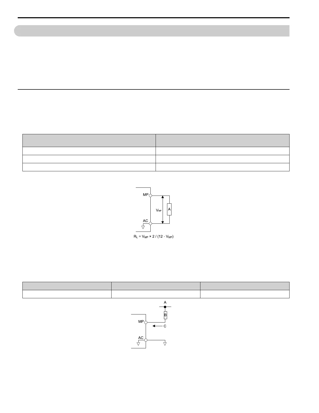
• Use for sourcing mode
The load impedance changes the voltage level of the pulse train output signal.
Load Impedance
R
L
(kΩ)
Output Voltage
V
MP
(V)
1.5 kΩ or more 5 V or more
4.0 kΩ or more 8 V or more
10 kΩ or more 10 V or more
Note:
Use the formula in Figure 5.5 to calculate the necessary load resistance (kΩ) to increase output voltage V
MP
(V).
A - Load Impedance
Figure 5.5 Wiring to Use Pulse Train Output in Sourcing Mode
• Use in sinking mode
The external power supply changes the voltage level of the pulse train output signal. Keep the voltage from an
external source between 10.8 Vdc to 16.5 Vdc. Adjust the load impedance to keep the current at 16 mA or lower.
External Power Supply (V) Load Impedance (kΩ) Sinking current (mA)
10.8 Vdc to 16.5 Vdc 1.0 kΩ or more 16 mA maximum
A - External power supply
B - Load Impedance
C - Sinking current
Figure 5.6 Wiring to Use Pulse Train Output in Sinking Mode

 Loading...


