Startup Procedure and Test Run
3
3.2 Overview of Keypad Components and Functions
YASKAWA TOEPYAIGA5002A GA500 DRIVE PROGRAMMING 463
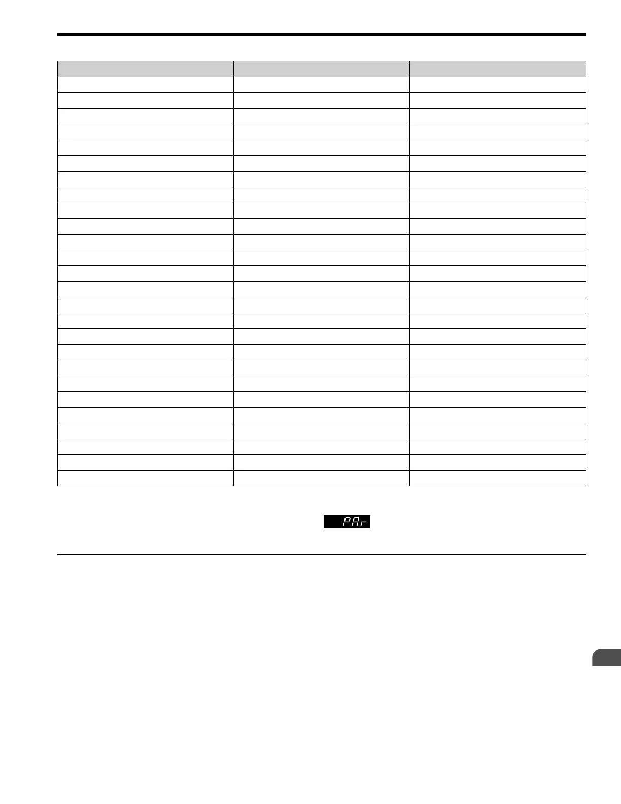
Table 3.3 Parameters in General-Purpose Setup Mode
User Parameter Parameter Name
A2-01 A1-02 Control Method Selection
A2-02 b1-01 Frequency Reference Selection 1
A2-03 b1-02 Run Command Selection 1
A2-04 b1-03 Stopping Method Selection
A2-05 C1-01 Acceleration Time 1
A2-06 C1-02 Deceleration Time 1
A2-07 C6-01 Normal / Heavy Duty Selection
A2-08 C6-02 Carrier Frequency Selection
A2-09 d1-01 Reference 1
A2-10 d1-02 Reference 2
A2-11 d1-03 Reference 3
A2-12 d1-04 Reference 4
A2-13 d1-17 Jog Reference
A2-14 E1-01 Input AC Supply Voltage
A2-15 E1-03 V/f Pattern Selection
A2-16 E1-04 Maximum Output Frequency
A2-17 E1-05 Maximum Output Voltage
A2-18 E1-06 Base Frequency
A2-19 E1-09 Minimum Output Frequency
A2-20 E1-13 Base Voltage
A2-21 E2-01 Motor Rated Current (FLA)
A2-22 E2-04 Motor Pole Count
A2-23 E2-11 Motor Rated Power
A2-24 H4-02 Terminal AM Analog Output Gain
A2-25 L1-01 Motor Overload (oL1) Protection
A2-26 L3-04 Stall Prevention during Decel
Note:
• When you change A1-02 [Control Mode Selection], the settings of some parameters automatically change.
• This manual also shows parameters that are not in Setup Mode. Use to set the parameters not shown in the Setup Mode.
• Display parameters change when the A1-06 [Application Preset] setting changes.
◆ Programming Mode
In Programming Mode, you can set parameters or do Auto-Tuning. This mode has 4 sub-modes for different
programming requirements:
• Verify Menu: Use this mode to examine and set the parameters that are not at default settings.
• Setup Mode: Use this mode to see and set the minimum parameters necessary for drive operation. Refer to Verify
and Set the Changed Parameters (Verify Menu) on page 464 for more information.
• Parameter Setting Mode: Use this mode to see and set all parameters.
• Auto-Tuning Mode: Use this mode to automatically set the motor parameters necessary for each control method.
■ Setup Mode
In Setup Mode, you can see and set the minimum parameters necessary for drive operation. Refer to Figure 3.7 for an
example.

 Loading...


