Parameter Details
2
2.3 b: Application
YASKAWA TOEPYAIGA5002A GA500 DRIVE PROGRAMMING 179
■ b3-56: InverseRotationSearch WaitTime
No.
(Hex.)
Name Description
Default
(Range)
b3-56
(3126)
InverseRotationSearch
WaitTime
Sets the wait time until the drive starts inverse rotation search after it completes forward search when
you do inverse rotation search during Current Detection Speed Search.
Determined by o2-04
(0.1 - 5.0 s)
■ b3-61: Initial Pole Detection Gain
No.
(Hex.)
Name Description
Default
(Range)
b3-61
(1B96)
Expert
Initial Pole Detection
Response Gain
Sets the responsiveness for initial motor magnetic pole calculation when A1-02 = 6 [Control Method
Selection = AOLV/PM]. Set b3-61 > 0.0 for an ordinary IPM motor.
5.0
(-20.0 - +20.0)
Used when n8-35 = 1 [Initial Pole Detection Method = High Frequency Injection]. Sets the responsiveness for initial
motor magnetic pole calculation. Set this parameter to a positive value for an ordinary monitor. When you use High
Frequency injection Tuning, it will automatically set this parameter.
◆ b4: Timer Function
The drive uses timers to delay activating and deactivating MFDO terminals.
Timers prevent sensors and switches from making chattering noise.
There are two types of timers:
• Timers that set a delay for timer inputs and timer outputs.
These timers delay activating and deactivating of the MFDIs and MFDOs.
To enable this function, set H1-xx = 18 [MFDI Function Selection = Timer Function], and set H2-01 to H2-03 = 12
[MFDO Function Selection = Timer Output].
• Timers that set a delay to activate and deactivate MFDO terminals.
These timers delay activating and deactivating MFDO terminals.
To enable this function, set delay times in parameters b4-03 to b4-08.
■ Timer Function Operation
• Timers that Set a Delay for Timer Inputs and Timer Outputs
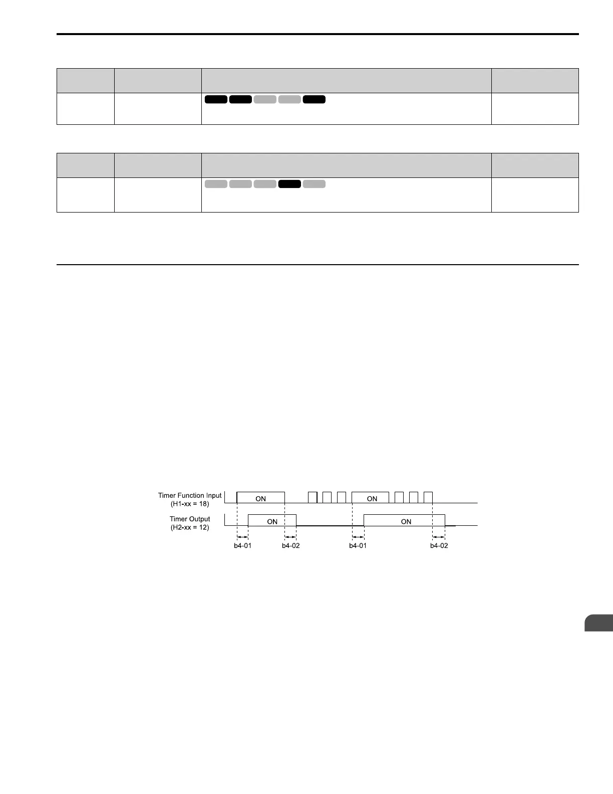
Triggers timer output if the timer input is active for longer than the time set in b4-01 [Timer Function ON-Delay
Time]. Triggers timer output late for the time set in b4-02 [Timer Function OFF-Delay Time]. Figure 2.19 shows an
example of how the timer function works.
Figure 2.19 Example of Timer Function Operation
• Setting On/Off-delay Time for MFDO
Figure 2.20 uses H2-01 terminals to show an example of how the timer function works. Use b4-03 [Terminal M1-
M2 ON-Delay Time] and b4-04 [Terminal M1-M2 OFF-Delay Time] to set this function.

 Loading...


