5.3 Control Circuit Wiring
506 YASKAWA TOEPYAIGA5002A GA500 DRIVE PROGRAMMING
Main Circuit Power Supply External 24 V Power Supply
o2-23
[External 24V Powerloss
Detection]
o2-26
[Alarm Display at Ext. 24V
Power]
Alarm Display
OFF ON - 0 [Disabled] “Ready” LED light flashes quickly
- 1 [Enabled] EP24v [External Power 24V
Supply]
■ Serial Communication Terminals
Refer to Table 5.6 for a list of serial communication terminals and functions.
Table 5.6 Serial Communication Terminals
Type Terminal Terminal Name Function (Signal Level)
Modbus Communication
D+ Communication input/output (+)
MEMOBUS/Modbus communications
Use an RS-485 cable to connect the drive.
Note:
Set DIP switch S2 to ON to enable the
termination resistor in the last drive in
a MEMOBUS/Modbus network.
• RS-485
• MEMOBUS/Modbus communication
protocol
• Maximum 115.2 kbps
D- Communication output (-)
AC Shield ground
0 V
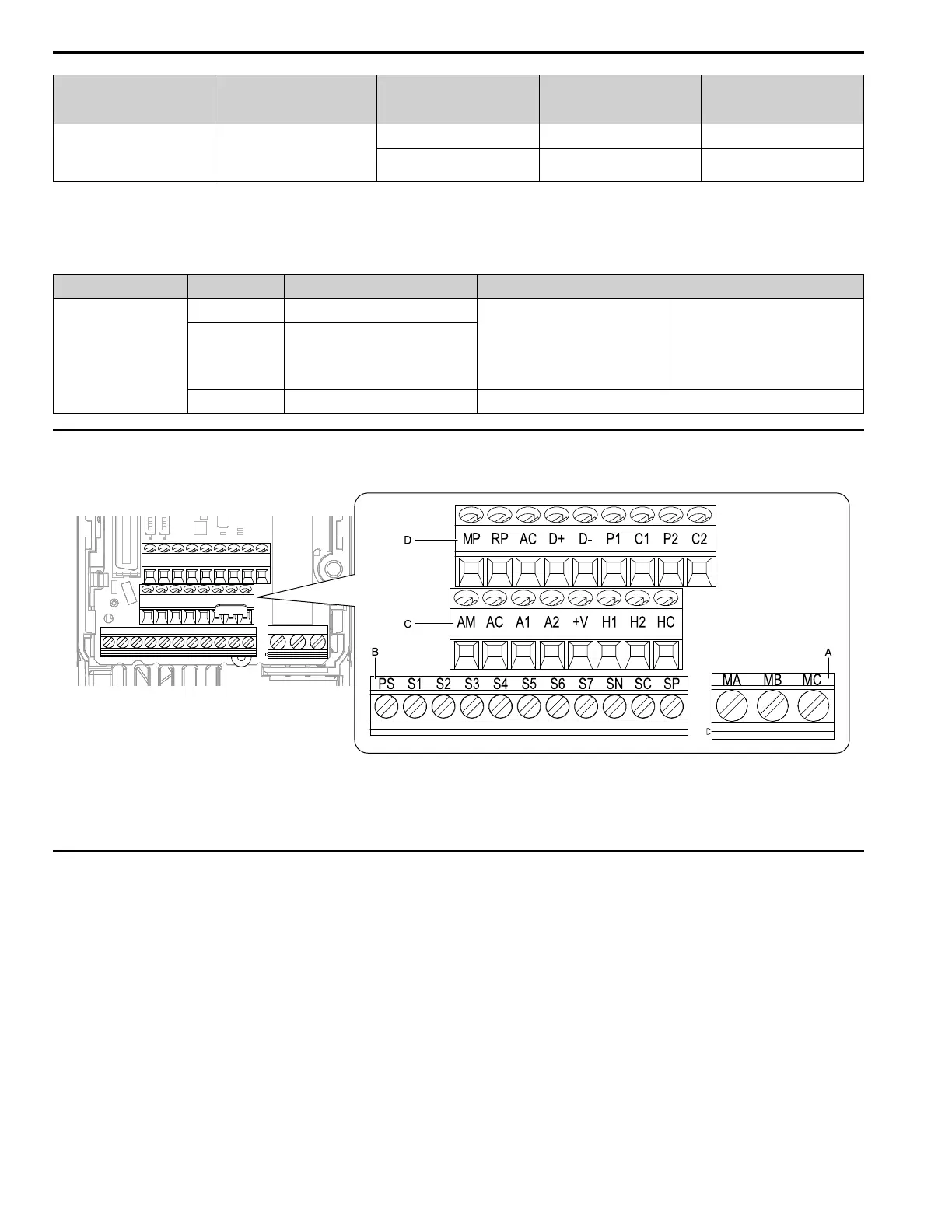
◆ Control Circuit Terminal Configuration
The control circuit terminals are in the positions shown in Figure 5.3.
A - Terminal block (TB2)
B - Terminal block (TB1-1)
C - Terminal block (TB1-2)
D - Terminal block (TB1-3)
Figure 5.3 Control Circuit Terminal Arrangement
◆ Switches and Jumpers on the Terminal Board
The terminal board has switches to adapt the drive I/Os to the external control signals as shown in Figure 5.4.
Set the switches to select the functions for each terminal.

 Loading...


