Parameter Details
2
2.8 H: Terminal Function Selection
YASKAWA TOEPYAIGA5002A GA500 DRIVE PROGRAMMING 349
If you set H5-22 = 1 and H1-xx = 62 [Speed Search from Fref] at the same time, the drive will detect oPE03 [Multi-
Function Input Setting Err].
■ H5-25: Function 5A Register 1 Selection
No.
(Hex.)
Name Description
Default
(Range)
H5-25
(1589)
RUN
Function 5A Register 1
Selection
Returns the contents of the specified MEMOBUS/Modbus communications register when responding
to the master device.
0044H (U1-05)
(0000H - FFFFH)
■ H5-26: Function 5A Register 2 Selection
No.
(Hex.)
Name Description
Default
(Range)
H5-26
(158A)
RUN
Function 5A Register 2
Selection
Returns the contents of the specified MEMOBUS/Modbus communications register when responding
to the master device.
0045H (U1-06)
(0000H - FFFFH)
■ H5-27: Function 5A Register 3 Selection
No.
(Hex.)
Name Description
Default
(Range)
H5-27
(158B)
RUN
Function 5A Register 3
Selection
Returns the contents of the specified MEMOBUS/Modbus communications register when responding
to the master device.
0042H (U1-03)
(0000H - FFFFH)
■ H5-28: Function 5A Register 4 Selection
No.
(Hex.)
Name Description
Default
(Range)
H5-28
(158C)
RUN
Function 5A Register 4
Selection
Returns the contents of the specified MEMOBUS/Modbus communications register when responding
to the master device.
0049H (U1-10)
(0000H - FFFFH)
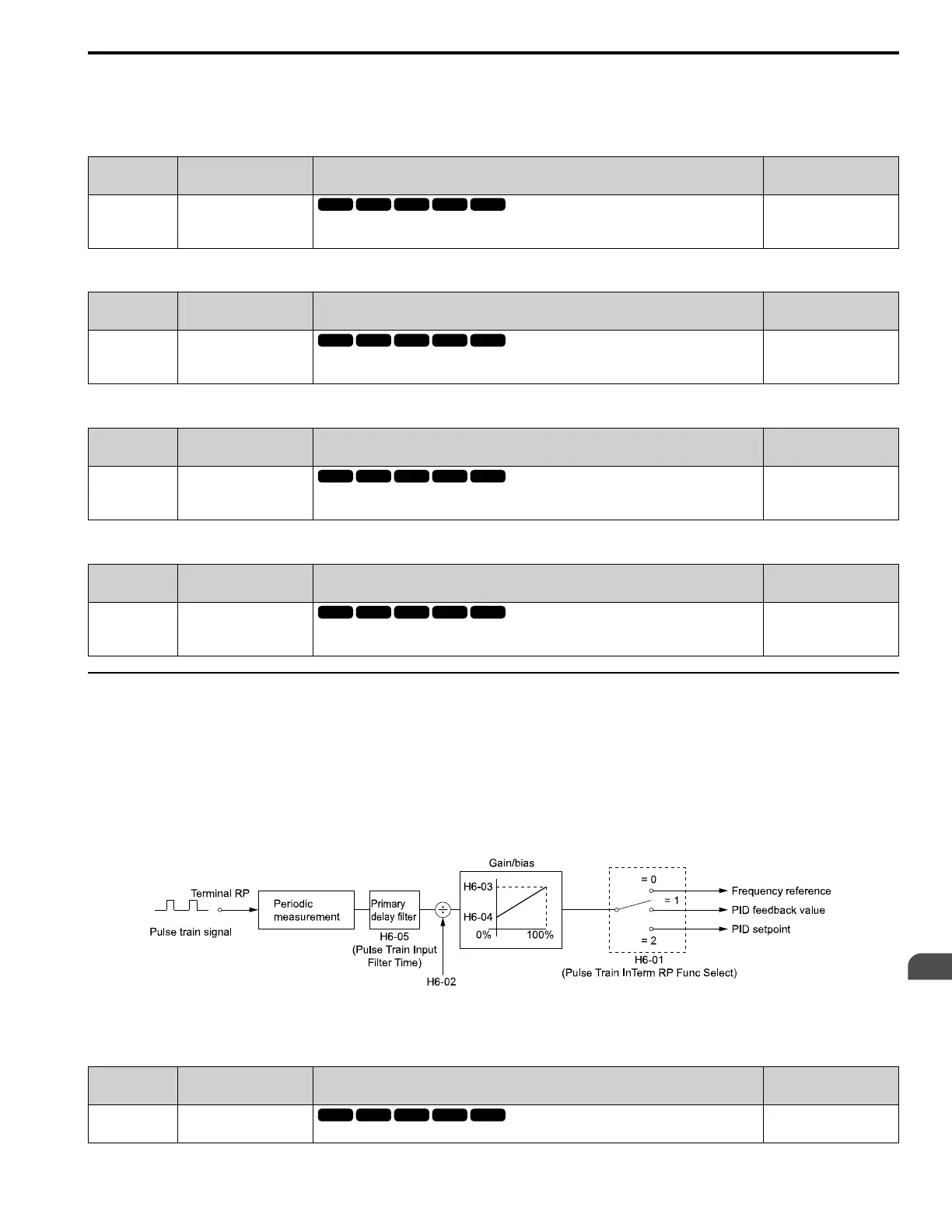
◆ H6: Pulse Train Input/Output
H6 parameters set the drive pulse train input and pulse train monitor. These parameters select input and monitor
parameters and adjust the pulse train frequency.
A pulse train signal with a maximum single pulse of 32 kHz can be input to the drive input terminal RP. You can use
the pulse train signal as the frequency reference, PID feedback value, PID setpoint value, and speed feedback for V/f
Control mode.
A pulse train signal with a maximum frequency of 32 kHz can be output from the drive output terminal MP as the
monitor value. Sinking mode and sourcing mode are supported.
Figure 2.92 Pulse Train Input Block Diagram
■ H6-01: Terminal RP Pulse Train Function
No.
(Hex.)
Name Description
Default
(Range)
H6-01
(042C)
Terminal RP Pulse Train
Function
Sets the function for pulse train input terminal RP.
0
(0 - 3)

 Loading...


