5.4 Control I/O Connections
510 YASKAWA TOEPYAIGA5002A GA500 DRIVE PROGRAMMING
Note:
Use tweezers or a jig with a tip width of approximately 0.8 mm (0.03 in) to set DIP switches.
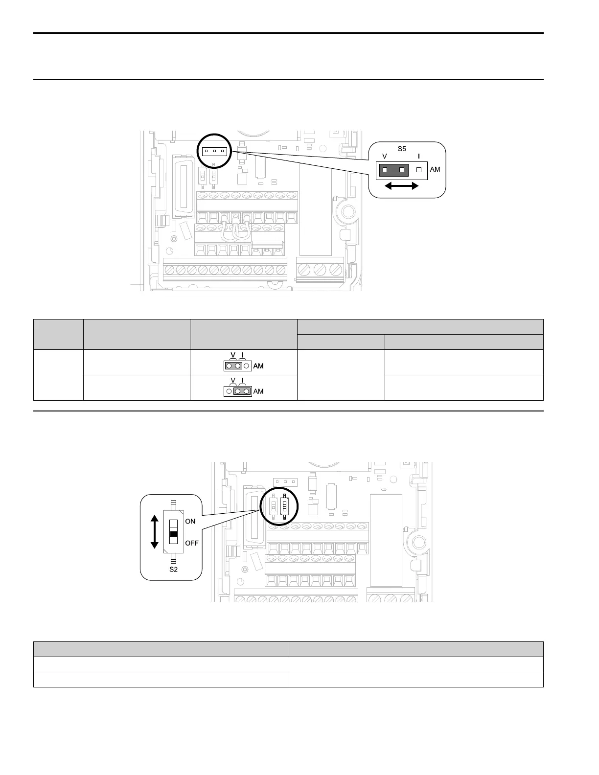
◆ Set the Output Signal for the MFAO Terminal AM
Set the signal type for terminal AM to voltage or current output. Use jumper S5 and H4-07 [Terminal AM Signal
Level Select] to set the signal type.
Figure 5.8 Location of Jumper Switch S5
Terminal Types of Output Signals Jumper S5
Parameter
No. Signal Level
AM
Voltage output
(Default)
H4-07
0: 0 V to 10 V
Current output 2: 4 mA to 20 mA
◆ Switch ON Termination Resistor for MEMOBUS/Modbus Communications
When the drive is the last slave in a MEMOBUS/Modbus communications, set DIP switch S2 to the ON position.
This drive has a built-in termination resistor for the RS-485 interface.
Figure 5.9 Location of DIP Switch S2
Table 5.9 MEMOBUS/Modbus Communications Termination Resistor Setting
DIP switch S2 Description
ON The built-in termination resistor is ON.
OFF (Default) The built-in termination resistor is OFF.

 Loading...


