Electrical Installation
5
5.4 Control I/O Connections
YASKAWA TOEPYAIGA5002A GA500 DRIVE PROGRAMMING 509
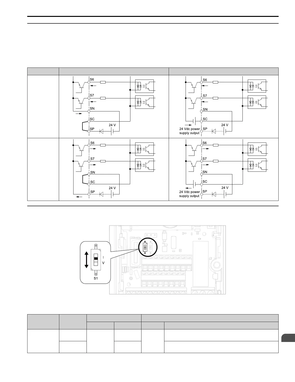
◆ Set Sinking Mode/Sourcing Mode
Close the circuit between terminals SC-SP and SC-SN to set the sinking mode/sourcing mode and the internal/
external power supply for the MFDI terminals. The default setting for the drive is internal power supply sinking
mode.
NOTICE: Damage to Equipment. Do not close the circuit between terminals SP-SN. If you close the circuits between terminals SC-
SP and terminals SC-SN at the same time, it will cause damage to the drive.
Mode Internal Power Supply (Terminal SN-SP) External 24 V power supply
Sinking Mode (NPN)
Sourcing Mode
(PNP)
◆ Set the Input Signal for the MFAI Terminal A2
Use terminal A2 to input a voltage or a current signal. Set the signal type as shown in Table 5.8.
Figure 5.7 Location of DIP Switch S1
Table 5.8 MFAI Terminal A2 Signal Settings
Terminal Input Signal
DIP Switch Settings Parameter
Switch Setting No. Signal Level
A2
Current input
S1
I
(Default)
H3-09
2: 4 mA to 20 mA/0% to 100% (input impedance: 250 Ω)
3: 0 mA to 20 mA/0% to 100% (input impedance: 250 Ω)
Voltage input V
0: 0 V to 10 V/0% to 100% (with zero limit) (input impedance: minimum 15 kΩ)
4: -10 V to +10 V/-100% to 100% (input impedance: minimum 15 kΩ)

 Loading...


