120 CHAPTER 6: IP ROUTING PROTOCOL OPERATION
Example: Typical RIP
Configuration
Networking Requirements
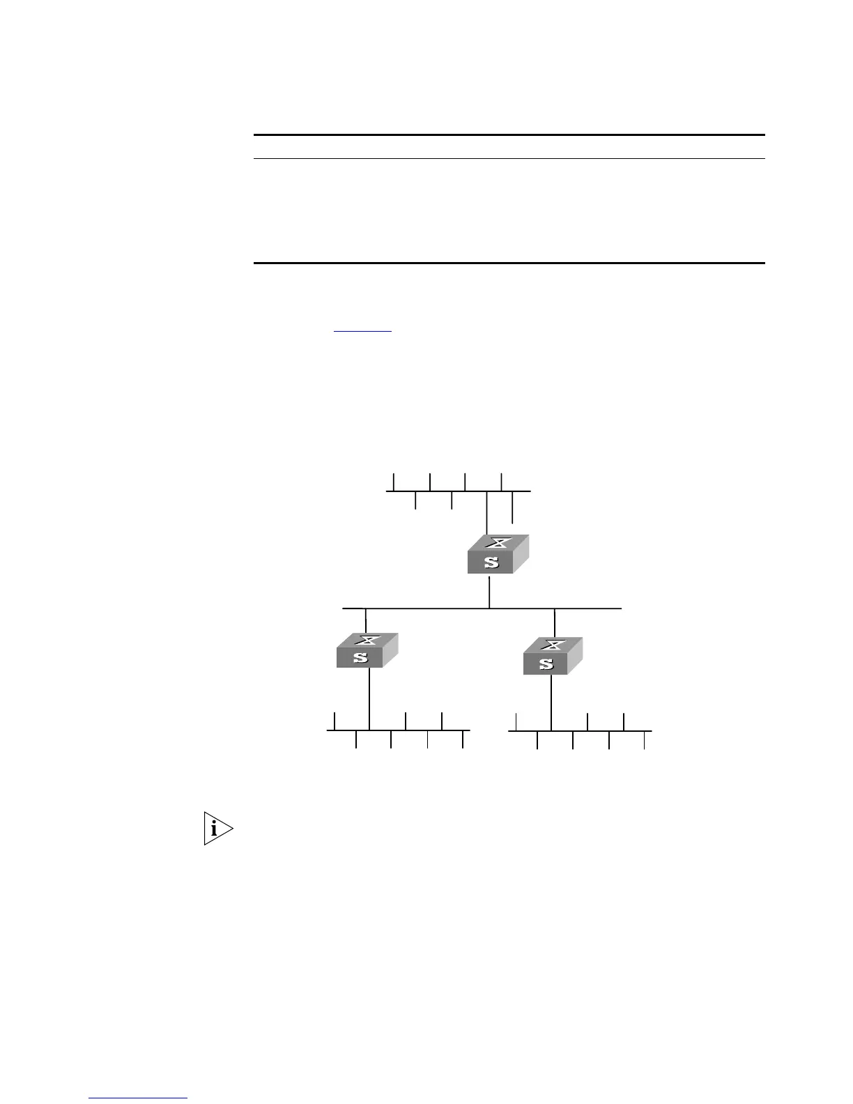
As shown in Figure 33, Switch C connects to the subnet 117.102.0.0 through the
Ethernet port. The Ethernet ports of Switch A and Switch B are connected to the
networks 155.10.1.0 and 196.38.165.0 respectively. Switch C, Switch A and
Switch B are connected via Ethernet 110.11.2.0. Correctly configure RIP to ensure
that Switch C, Switch A and Switch B can interconnect.
Networking Diagram
Figure 33 RIP configuration networking
Configuration Procedure
The following configuration only shows the operations related to RIP. Before
performing the following configuration, please make sure the Ethernet link layer
can work normally and the IP addresses for the VLAN interfaces are configured.
1 Configure RIP on Switch A
[Switch A]rip
[Switch A-rip]network 110.11.2.0
[Switch A-rip]network 155.10.1.0
2 Configure RIP on Switch B
[Switch B]rip
[Switch B-rip]network 196.38.165.0
[Switch B-rip]network 110.11.2.0
Enable the debugging of RIP receiving packet debugging rip receive
Disable the debugging of RIP receiving packet undo debugging rip receive
Enable the debugging of RIP sending packet debugging rip send
Disable the debugging of RIP sending packet undo debugging rip send
Reset the system configuration parameters of RIP reset
Table 121 Displaying and Debugging RIP
Operation Command
Ethernet
Network address:
110.11.2.2/24
Network address:
117.102.0.0/16
Network address:
196.38.165.0/24
Interface address:
110.11.2.1/24
Interface address:
117.102.0.1/16
Interface address:
155.10.1.1/24
Network address:
155.10.1.0/24
Interface address:
196.38.165.1/24
SwitchA
SwitchB
SwitchC
 Loading...